Air bushing linear stage system

a stage system and linear technology, applied in the field of air bushing linear stage system, can solve the problems of reducing the accuracy of machining, increasing the number of errors, and inducing additional errors by machining accuracy errors

Active Publication Date: 2010-04-22
ALIO INDS
View PDF3 Cites 6 Cited by
  • Summary
  • Abstract
  • Description
  • Claims
  • Application Information

AI Technical Summary

Problems solved by technology

Once again vertical positioning of the wafer is critical since overdriving the probes may damage them.
Many versions of Z wedge designs exist but this design inherently has many errors associated with it.
Bearings always have some dimensional error or parallelism errors that are included in the motion.
Additional errors are induced by m

Method used


Image

  • Air bushing linear stage system
  • Air bushing linear stage system
  • Air bushing linear stage system

Examples


Embodiment Construction

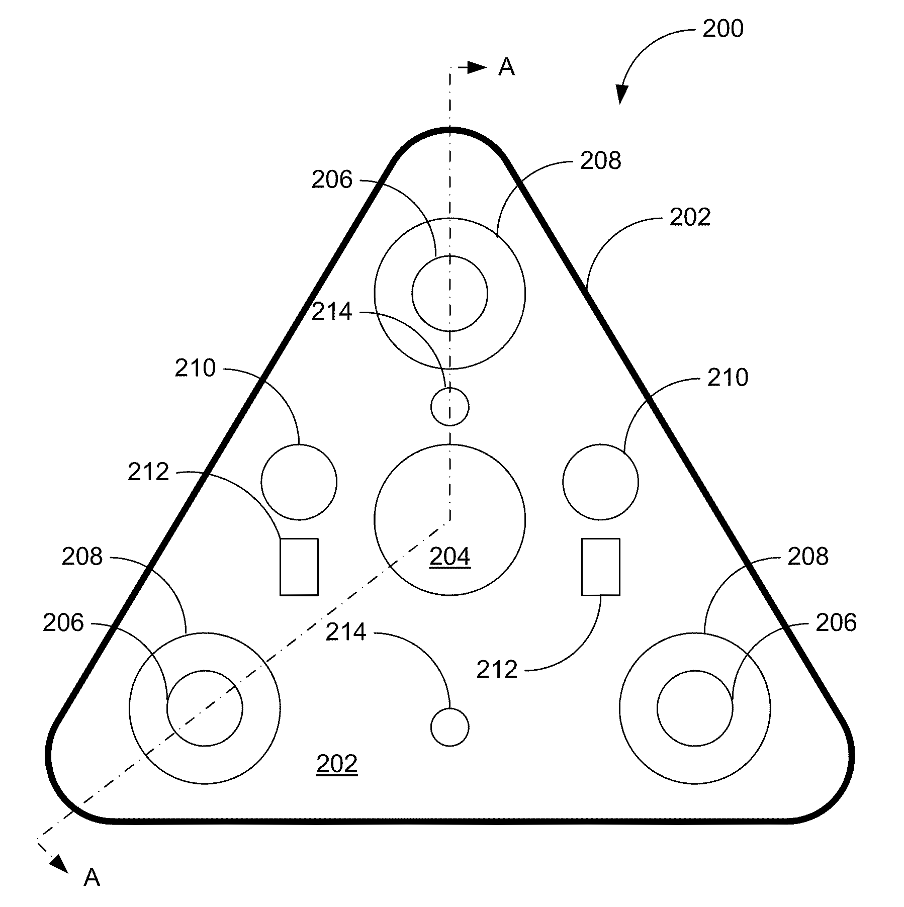
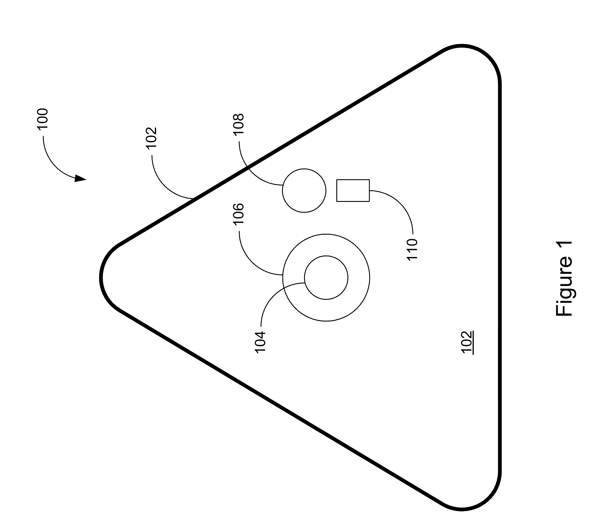
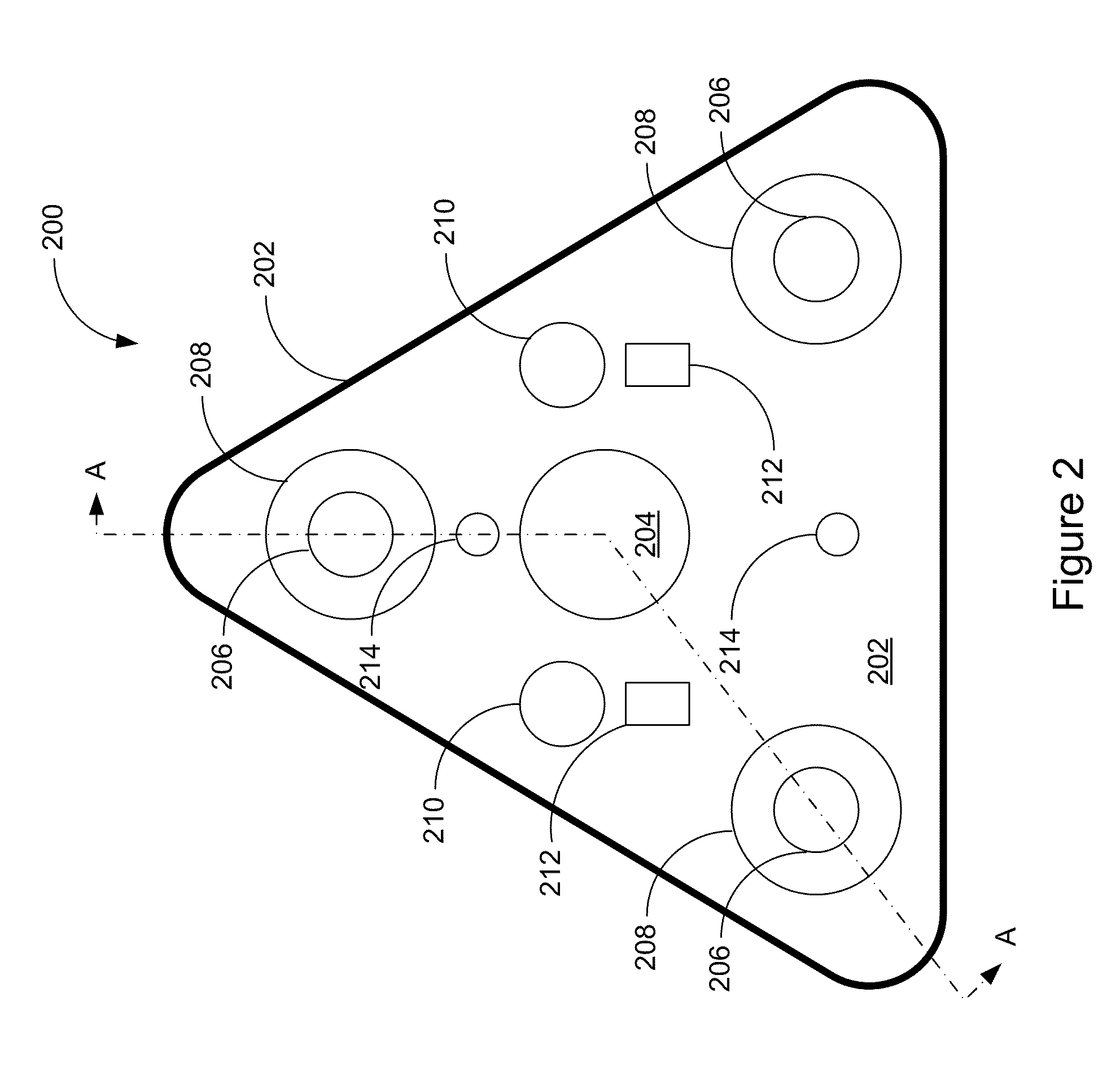
[0025]A linear stage system comprises multiple air bushings, shafts, encoders, motors, and a controller, which are all mounted on a base. The air bushings support a carriage plate. The linear stage system may also comprise pneumatic counter balances to permit easy user adjustment for various applications and a central thru aperture that provides an added capability for additional equipment mounted to the base. The motors, air bushings, and counter balances are all placed symmetrically within the structure to ensure all applied forces and restraint are balanced. Other embodiments may include placing the motors, air bushing, and counter balances asymmetrically within the structure. Depending on how the linear stage system is configured, the carriage plate may move in different linear dimensions from the base.

[0026]FIG. 1 is a top view of an example of a linear stage 100. The linear stage 100 of FIG. 1 is triangular in shape and is comprised of a stationary base (not shown beneath carr...


PUM


Abstract

A linear stage system is provided. The linear stage system includes a base, a carriage plate, a first shaft, a first air bushing coupled to the base, a first motor coupled to the base and the carriage plate, and a first position encoder. The first air bushing is configured to support the carriage plate via the first shaft, wherein the first air bushing utilizes the first shaft as a guide surface and is configured to support positioning of the carriage plate along an axis. The first motor is configured to create a linear motion parallel to the axis in a first motor element coupled to the carriage plate to position the carriage plate along the axis in response to a first control signal. The first position encoder is configured to determine a position of the carriage plate relative to the base.

Description

RELATED APPLICATIONS [0001]This application hereby claims the benefit of and priority to U.S. Provisional Patent Application No. 61 / 107,418, titled “AIR BUSHING LINEAR STAGE SYSTEM”, filed on Oct. 22, 2008, and which is hereby incorporated by reference in its entirety.TECHNICAL BACKGROUND [0002]Linear stage systems are utilized for precision motion in linear directions. Linear stage systems are commonly used in manufacturing processes, such as semiconductor manufacturing. A linear stage system may be used to position a silicon wafer at a specific position so that a mask image is in focus on the wafer surface. In such photolithography applications focus is critical and is accomplished by ensuring that the surface of the wafer is in a precise position for best possible focus. Other applications for linear stage systems may arise in testing semiconductors where a wafer must be lifted against a set of probes. Once again vertical positioning of the wafer is critical since overdriving the...

Claims


Application Information

Patent Timeline
IPC IPC(8): H02K41/02
CPCG03F7/70716H02P25/06G03F7/70758
Inventor HENNESSEY, CLEMENT WILLIAMBROWN, NATHAN LYONS
Owner ALIO INDS
Why Eureka
Try Eureka