
Airbag apparatus

a technology for airbags and apparatuses, applied in the direction of vehicular safety arrangments, pedestrian/occupant safety arrangements, vehicle components, etc., to achieve the effect of improving gas seal properties, preventing gas leakage, and improving gas seal properties

Inactive Publication Date: 2010-04-22
TOYODA GOSEI CO LTD
View PDF4 Cites 12 Cited by
  • Summary
  • Abstract
  • Description
  • Claims
  • Application Information

AI Technical Summary

Benefits of technology

[0007]An object of the present invention is to provide an airbag apparatus that has improved gas seal at an insert hole of an airbag for receiving an inflator in order to prevent gas leak from a gap which would otherwise be formed between the airbag and inflator due to a tensile force exerted upon airbag deployment.
[0009]The airbag apparatus includes a housing, an inflator secured to the housing and having a generally columnar shape, the inflator including at a first end discharge ports for emission of inflation gas, and an airbag secured to and housed in the housing in a folded up configuration. The airbag includes a bag body that constitutes an outer circumferential wall of the airbag and is inflatable with inflation gas. The bag body includes an insert hole that receives the inflator, such that a region of the inflator on the side of the first end provided with the discharge ports is housed inside the airbag whereas a region of the inflator on the side of a second end projects out of the insert hole. The region of the inflator on the side of the first end secures the bag body to the housing. The airbag further includes a sealing cloth having flexibility and so connected to the bag body as to cover a peripheral area of the insert hole on an inner circumference of the bag body for providing gas seal at the insert hole of the bag body. The sealing cloth includes a through hole for receiving the inflator on a location corresponding to the insert hole of the bag body and a slit that encircles the through hole generally wholly in a circumferential direction and enables relative slip movement between a peripheral area of the through hole on the sealing cloth and the peripheral area of the insert hole on the bag body in generally radial directions about the through hole.
[0011]However, the airbag of the airbag apparatus of the invention includes a sealing cloth arranged to cover the peripheral area of the insert hole on the inner circumference of the bag body, and the sealing cloth includes around the through hole for receiving the inflator a slit that encircles the through hole generally wholly in a circumferential direction. With this configuration, even in the event that the tension force acts on the peripheral area of the insert hole toward the deployment direction of the airbag and tries to pull the sealing cloth as well, the sealing cloth deals with the tensile force by opening the slit, and the peripheral area of the through hole of the sealing cloth located between the slit and the through hole is not pulled by the tensile force and stays in close contact with the outer circumference of the inflator. That is, the peripheral area of the through hole of the sealing cloth slips relative to the peripheral are of the insert hole of the bag body. As a result, the sealing cloth covers the gap formed between the inner circumference of the insert hole and the outer circumference of the inflator by the peripheral area of the through hole. Moreover, since the slit is formed to encircle the through hole generally wholly in a circumferential direction, even in the event that the direction of action of the tensile force varies during airbag deployment, for example changes toward a direction generally orthogonal to the deployment direction of the airbag, the peripheral area of the through hole is not pulled by the tensile force and covers a gap formed between the inner circumference of the insert hole and the outer circumference of the inflator. As a consequence, the insert hole of the bag body is prevented from leaking inflation gas which has once flown into the bag body, and thus improving gas seal property in the periphery of the insert hole.
[0012]Therefore, the airbag apparatus of the invention has improved gas seal at the insert hole of the airbag for receiving an inflator and prevents gas leak from a gap which would otherwise be formed between the airbag and inflator due to a tensile force exerted upon airbag deployment.
[0014]Also with this configuration, even in the event that the tension force acts on the peripheral area of the insert hole toward the deployment direction of the airbag and tries to pull the sealing cloth as well, the sealing cloth deals with the tensile force by stretching out in such a manner as to take up any of the slacks, such that the peripheral area of the through hole of the sealing cloth is not pulled by the tensile force and stays in close contact with the outer circumference of the inflator body. As a result, the sealing cloth covers a gap formed between the inner circumference of the insert hole and the outer circumference of the inflator by the peripheral area of the through hole. Moreover, since the sealing cloth is sewn to the bag body at at least three portions on generally radial locations about the through hole while provided with the slack relative to the bag body on each hem, even in the event that the direction of action of the tensile force varies during airbag deployment, for example orthogonally, the peripheral area of the through hole is not pulled by the tensile force and the peripheral area covers the gap formed between the inner circumference of the insert hole and the outer circumference of the inflator body. As a consequence, the insert hole of the bag body is prevented from leaking inflation gas which has once flown into the bag body, and thus improving gas seal property in the periphery of the insert hole.
[0015]Therefore, the airbag apparatus of the invention has improved gas seal at the insert hole of the airbag for receiving an inflator and prevents gas leak from between the airbag and inflator.

Problems solved by technology

However, this configuration that the slack of the seal cloth is formed only on the side of the peripheral area of the fitting hole on which a tensile force acts can fail to deal with such an event that the direction of action of the tensile force varies during airbag deployment, for instance orthogonally.

Method used


Image

  • Airbag apparatus
  • Airbag apparatus
  • Airbag apparatus

Examples


first embodiment

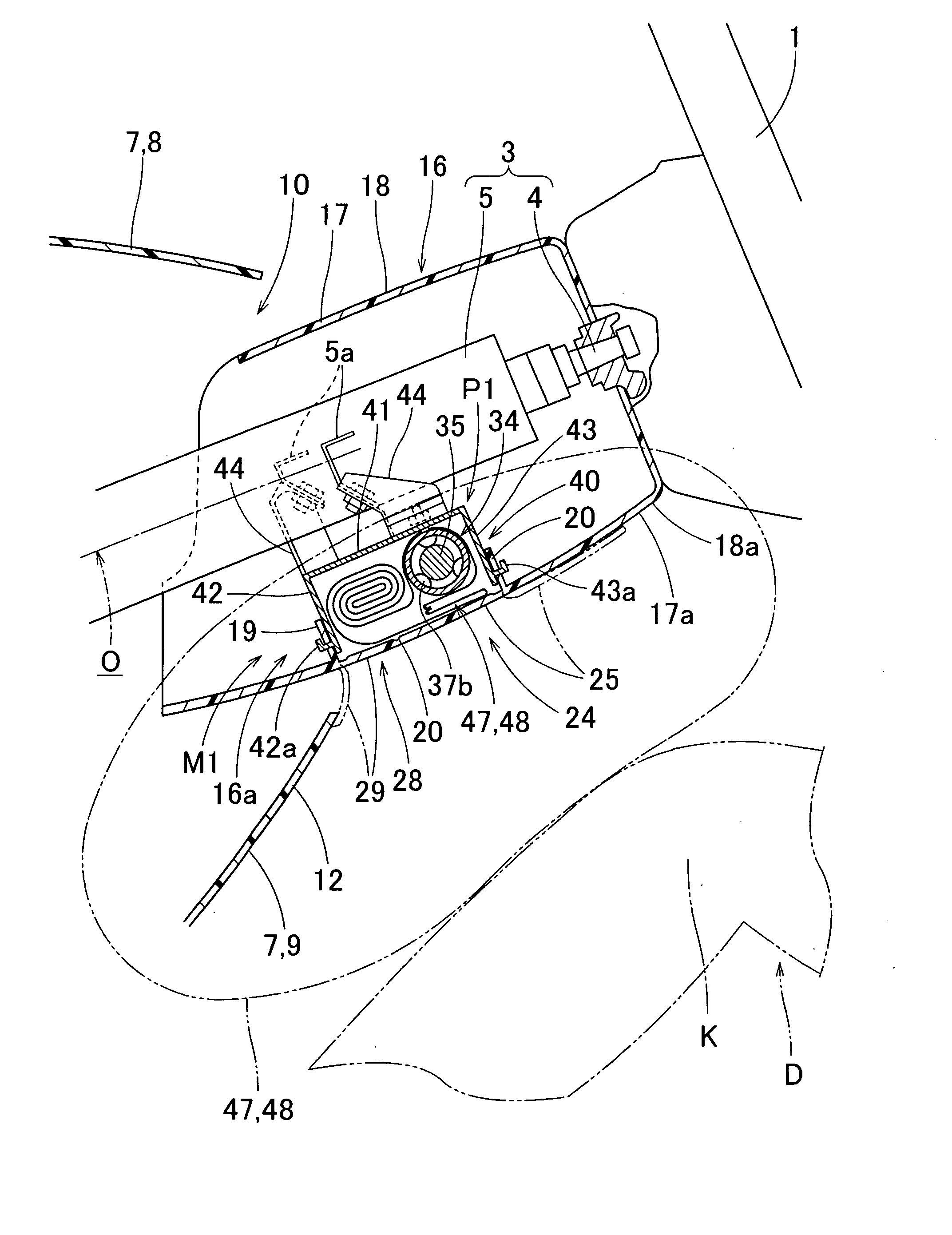
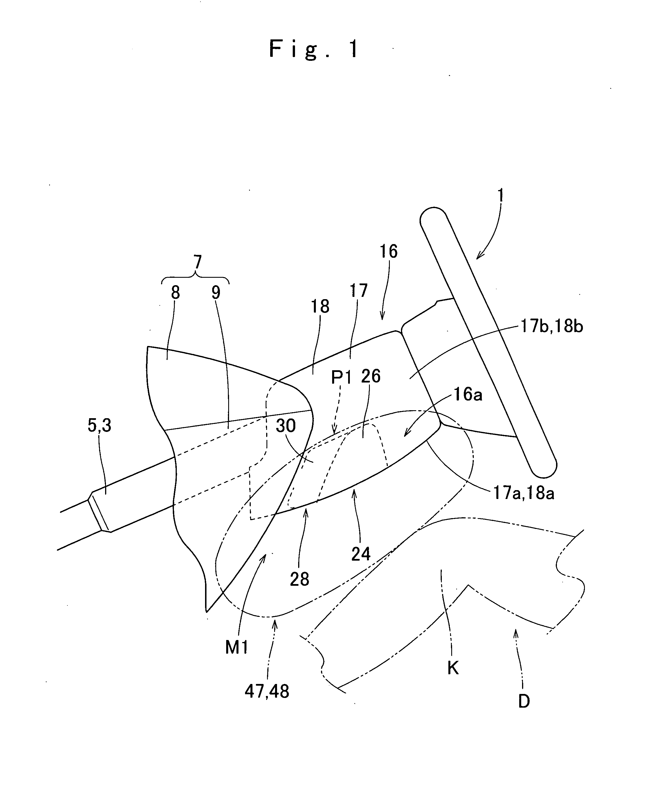
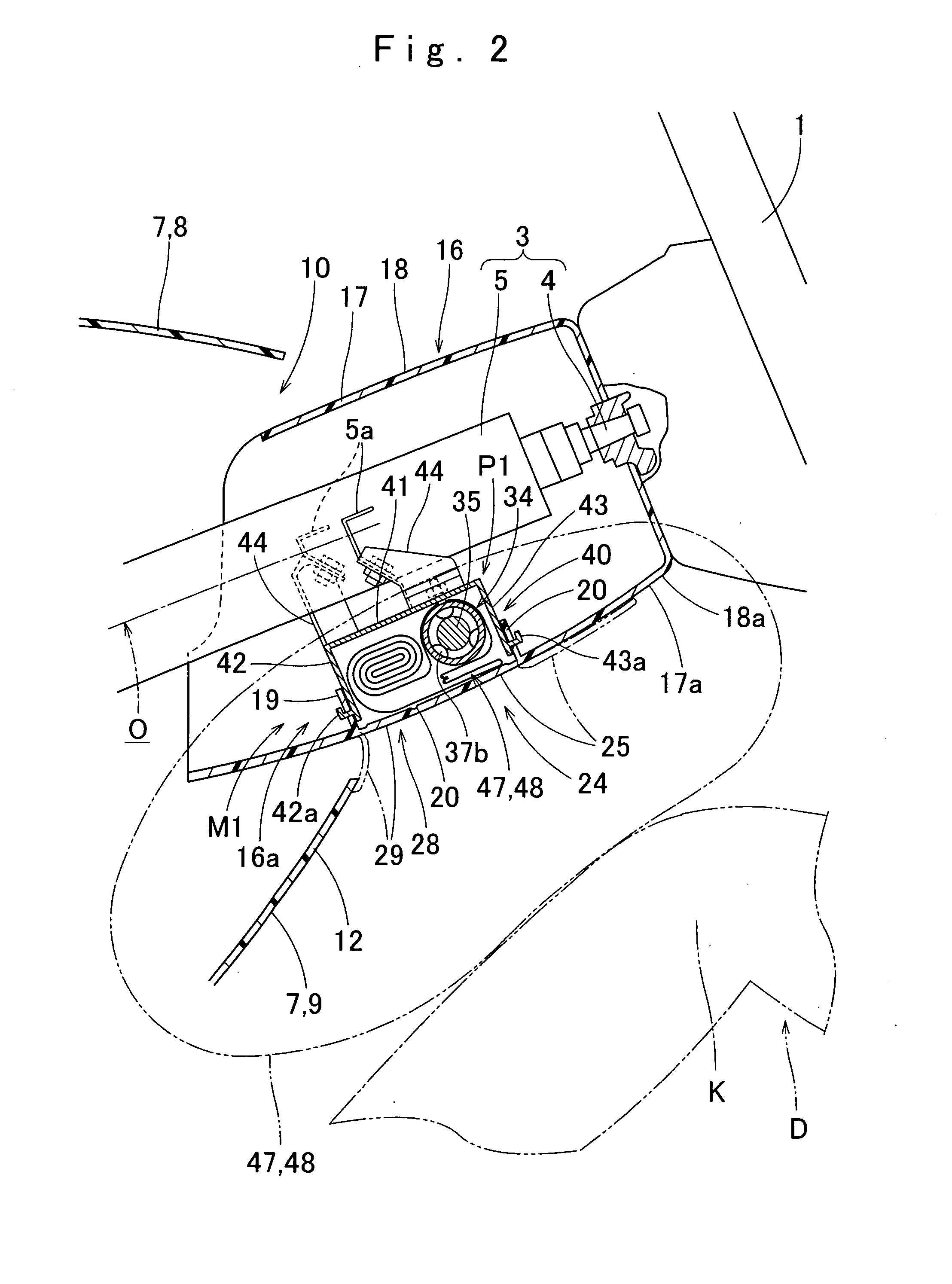
[0039]As shown in FIGS. 1 and 2, a knee-protecting airbag apparatus M1 according to the invention is mounted on a steering column 3 and housed in a lower space 16a inside the column cover 16 with the aim of protection of knees K (KR and KL) of a driver D seated in a driver's seat. As shown in FIGS. 2 and 3, the airbag apparatus M1 includes an airbag 47 and an inflator 34 that supplies inflation gas to the airbag 47, and is housed in a housing area P1 located in the lower space 16a of the column cover 16.

[0040]Unless otherwise specified, front / rear, up / down and left / right directions referred to in this specification are based on the axial direction O (FIG. 2) of the steering column 3. Front / rear direction is intended to refer to a front / rear direction extending along the axial direction of the steering column 3. Up / down direction is intended to refer to an up / down direction extending perpendicularly to the axial direction, and left / right direction is intended to refer to a left / right...

second embodiment

[0069]The sealing cloth 58 can be coupled to the bag body 48 only by laying the cloth 58 on a predetermined location of the column side panel 50 and stitching the front edge 58a and rear edge 58b to the panel 50. Preparation is therefore easier than a later-described sealing cloth 92 of second embodiment and thus simplifying the manufacturing process.

[0070]The second embodiment of the invention is now described. A knee-protecting airbag apparatus M2 according to the second embodiment is housed in a lower space 16a inside the column cover 16 as in the first embodiment, as shown in FIG. 14. The airbag apparatus M2 includes an airbag 91, an inflator 76 and a case 83 that houses the airbag 91 and inflator 76. The airbag apparatus M2 has a generally identical structure to that of the airbag apparatus M1 of the first embodiment except in the configuration of a sealing cloth 92 applied to the airbag 91 and in the orientation of a body 35 of the inflator 76. Moreover, the column cover 16 ha...


PUM


Abstract

An airbag apparatus includes an airbag that includes a bag body provided with an insert hole for receiving an inflator and a sealing cloth arranged to cover a peripheral area of the insert hole. The sealing cloth includes on the location corresponding to the insert hole a through hole for receiving the inflator. The sealing cloth further includes around the through hole a slit that encircles the through hole generally wholly in a circumferential direction and enables relative slip movement between a peripheral area of the through hole on the sealing cloth and the peripheral area of the insert hole on the bag body in generally radial directions about the through hole

Description

[0001]The Present application claims priority from Japanese Patent Application No. 2008-269729 of Tanaka et al., filed on Oct. 20, 2008, the disclosure of which is hereby incorporated into the present application by reference.BACKGROUND OF THE INVENTION[0002]1. Field of the Invention[0003]The present invention relates to an airbag apparatus mountable on a vehicle that includes an inflatable airbag and an inflator that supplies inflation gas to the airbag. More particularly, the invention relates to an airbag apparatus suitable for use as a knee-protecting or a side impact airbag apparatus in which an inflator is put through an insert hole of an airbag such that a first end of the inflator is located outside of the airbag whereas a second end of the inflator having gas discharge ports is housed inside the airbag.[0004]2. Description of Related Art[0005]In a knee-protecting or a side impact airbag apparatus, an airbag is secured to an installation location at its portion dislocated fr...

Claims


Application Information

Patent Timeline
IPC IPC(8): B60R21/16B60R21/20B60R21/217B60R21/231
CPCB60R21/2032B60R21/206B60R21/2165B60R2021/23382B60R21/239B60R2021/23169B60R21/2338
Inventor TANAKA, KOKIOYABU, MASANORINAKAYAMA, KAZUHIROOGATA, TETSUYAMATSUURA, HIROKAZU
Owner TOYODA GOSEI CO LTD
Learn More