Eureka AIR delivers breakthrough ideas for toughest innovation challenges, trusted by R&D personnel around the world.

Clamp For A Medical Implant And A Method For Using The Same

a technology for medical implants and clamps, which is applied in the field of clamps, can solve the problems of deformation of the bone, inability to use children and young adults, growth disturbances or growth arrest of the growth plates, etc., and achieve the effect of reducing the movement of the end

Inactive Publication Date: 2010-04-15
DELBELLO DAMON
View PDF12 Cites 7 Cited by
  • Summary
  • Abstract
  • Description
  • Claims
  • Application Information

AI Technical Summary

Benefits of technology

[0019]Accordingly, it is an object of the present invention to provide a device that reduces movement of an end of an intramedullary rod protruding from an insertion site in a bone.
[0020]Accordingly, it is another object of the present invention to provide a device that reduces movement of an end of an intramedullary rod protruding from an insertion site in a bone, wherein the movement is of the rod is reduced relative to the insertion site.
[0021]It is yet another object of the present invention to provide a device that reduces movement of a distal end of an intramedullary rod protruding from an insertion site in a bone, wherein the movement is of the rod is reduced relative to said device.
[0022]It is yet another object of the present invention to provide a device that reduces movement of a distal end of an intramedullary rod protruding from an insertion site in the bone wherein rotation movement of the intramedullary rod is reduced along its axis.
[0023]It is yet another object of the present invention to provide a device for reducing movement of an end of an intramedullary rod protruding from a bone, wherein a single clamping device may be used with intramedullary rods having different diameters.

Problems solved by technology

A disadvantage the intramedullary rod systems described above is that they cannot be used in children and young adults due to the risk of bone and limb deformity resulting from continued growth of the bone while the intramedullary rod remains in the medullary cavity bone.
If an intramedullary rod remains in a bone of a child or young adult, however, bone it could cause deformation of the bone.
In addition, the placement of such a device would require drilling large holes through the growth plate resulting in growth disturbances or growth arrest of the growth plates.
This configuration produces flexural and translational stability and some limited axial and rotational stability.
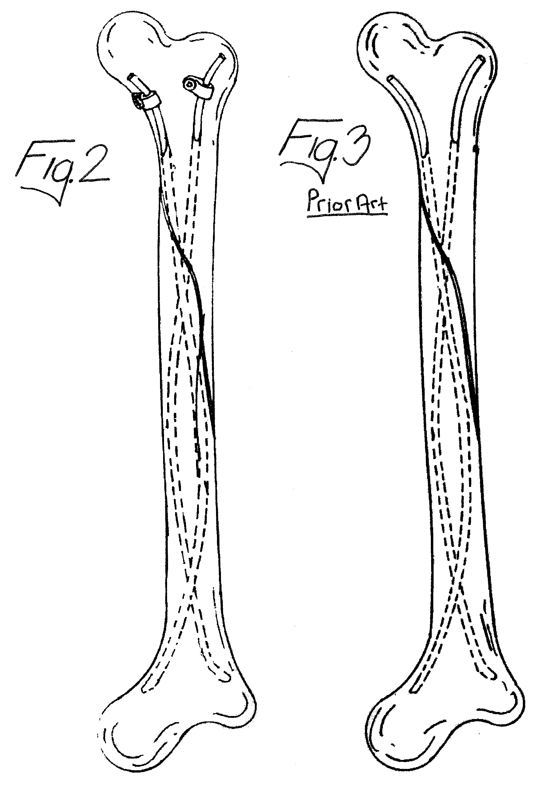
One known disadvantage of the above described solution is that the end of the intramedullary rod 30 protruding from the insertion site 18 is not fixed to the bone allowing the protruding end of the intramedullary rod 30 to move relative to the bone.
Movement of the intramedullary rod 30 is not desirable because it can adversely affect the manner in which the fracture heals.
For example, substantial movement of the protruding end of the intramedullary rod 30 may result in movement of the fracture setting, resulting in an improperly set fracture.
One known disadvantage of the end cap anchoring devices is that during installation lateral and rotation thrust caused by the turning of the end cap required to engage the threads with the bone at the insertion site 18 causes undesirable transverse movement of the fractured parts of the long bone due to the tendency of the intramedullary rod 30 to rotate inside the medullary cavity.
Another known disadvantage of such end cap devices is the increased expense and logistical problems caused by the requirement to store a large number of different sized devices.
Another disadvantage of the end cap solution is that the installation may adversely affect the setting or placement of the intramedullary rod during installation by pushing the rod too far into the medullary cavity.
Another disadvantage of the known end caps is that while the end caps prevent the rod from sliding distally outward through the insertion site from the medullary cavity, they do not prevent the rod from sliding further into the medullary cavity.
Another disadvantage of known end caps is that while the end cap prevents the intramedullary rod from sliding back through the insertion site, the end cap does not prevent axial rotation of the installed intramedullary rod.

Method used


Image

  • Clamp For A Medical Implant And A Method For Using The Same
  • Clamp For A Medical Implant And A Method For Using The Same
  • Clamp For A Medical Implant And A Method For Using The Same

Examples


Embodiment Construction

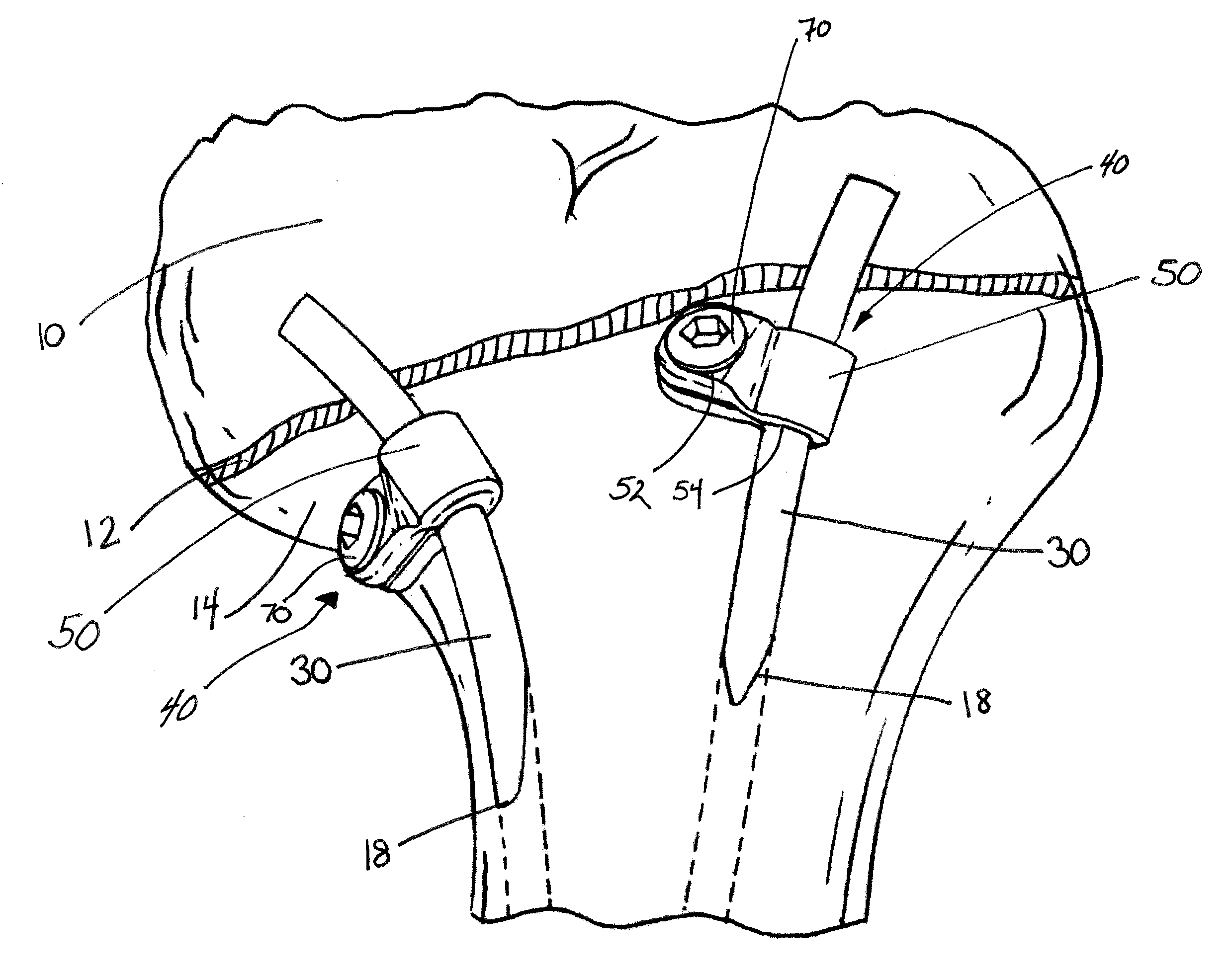
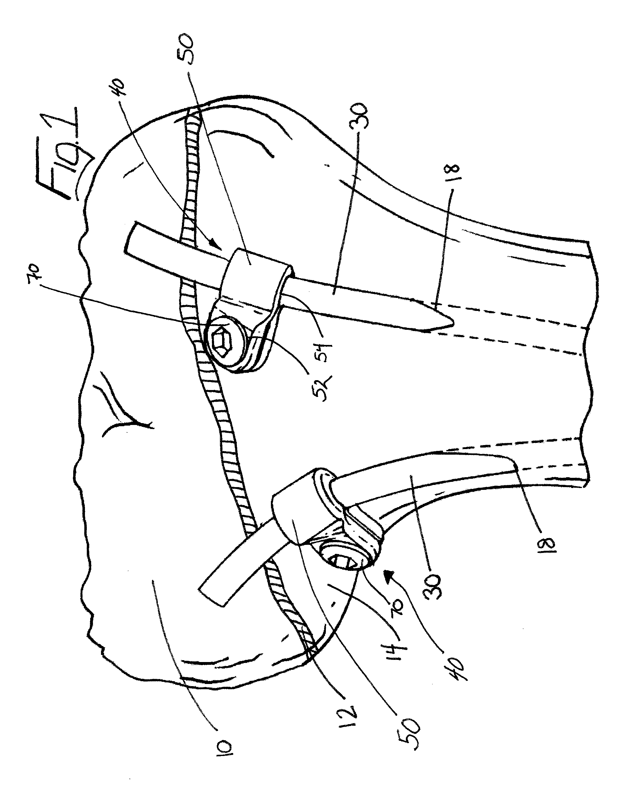
[0036]In reference to FIG. 1, one embodiment of the present invention for reducing movement of an end of an intramedullary rod 30 protruding from an insertion site 18 in a bone 10 is shown. The device 40 includes at least one clamp 50 for securing the intramedullary rod 30 protruding from the insertion site 18 in the bone 10. The securing device 40 further includes a bone anchor 70 for securing the clamp 50 to the bone 10 at a location away from the insertion site 18. Preferably the bone anchor 70 comprises a bone screw 70; however it should be understood that many different types of bone anchors may be used to secure the clamp 50 to the bone 10.

[0037]The clamp 50 comprises at least two openings 52, 54. The first opening 54 is for receiving the protruding end 32 of the intramedullary rod 30. The second opening 52 is for receiving the bone screw 70. As the bone screw 70 is inserted through the second opening 52 and into the bone 10, the bone screw 70 secures the clamp 50 relative to ...


PUM


Abstract

A clamping device for use with a medical instrument is disclosed. Specifically, a clamping device for use with an intramedullary rod in children and young adults. The intramedullary rod is inserted into the medullary cavity of a long bone and a portion of the rod protrudes. The disclosed clamping device secures the protruding end of the rod, and reduces movement of the rod in all directions relative to the insertion site of the rod.

Description

FIELD OF THE INVENTION[0001]The present invention relates to a device for stabilizing a medical implant and a method for using the same. More specifically, the present invention relates to a clamp for securing an end of an intramedullary rod that protrudes from an insertion site in a bone so that movement of the end of the intramedullary rod is reduced.BACKGROUND OF THE INVENTION[0002]The use of intramedullary rods (also known as intramedullary nails, and elastic nails) to treat and repair fractures in bones, such as the femur and tibia, is well known. For example U.S. Pat. No. 4,169,470 to Ender et al. discloses an elongated relatively thin, elastic, flexible and resilient rod for emplacement in and along the medullary canal of a fractured bone.[0003]In typical methods of fracture repair, an intramedullary rod is inserted into and along the axis of the medullary cavity of a long bone so that the rod passes across a fracture in the bone. The medullary cavity is the central cavity of...

Claims


Application Information

Patent Timeline
IPC IPC(8): A61B17/04A61B19/00
CPCA61B17/7241
Inventor DELBELLO, DAMON
Owner DELBELLO DAMON
Why Eureka
Eureka Blog
Learn More