Eureka AIR delivers breakthrough ideas for toughest innovation challenges, trusted by R&D personnel around the world.

Method and device for reading electrical charges produced by a photo-detector, and detector comprising such devices

a photo-detector and photo-detector technology, applied in the field of photo-diodes, can solve the problems of limited size of the integrating capacitor, limited operation of the read device, and the inability to read and deliver a voltage in the matrix read by scanning, so as to achieve the effect of increasing the dynamic of the read noise without degrading the read nois

Active Publication Date: 2010-04-15
DE DETECTEURS INFRAROUGES - SOFRADIR
View PDF20 Cites 2 Cited by
  • Summary
  • Abstract
  • Description
  • Claims
  • Application Information

AI Technical Summary

Benefits of technology

[0031]The purpose of the present invention is to propose a method and a device for reading the charges produced by a photo-detector of a matrix detector that allows the dynamic thereof to be increased without degrading the read noise.
[0035]This intermediate measurement obtained with a shorter integration time covers a dynamic located above the prior art dynamic. It thus complements the prior art dynamic and the overall dynamic of the detector is thus extended.

Problems solved by technology

In fact, reading and delivering a voltage in a matrix read by scanning takes some time.
A first limitation on the operation of the read device so described stems from the limited size of the integrating capacitor 14.
Indeed, the surface usually allocated to the read device 10 is limited for reasons of compactness.
The detector dynamic is thus also limited.
A second limitation relates to the read noise.
The read device, in its conventional operation, therefore sees its dynamic limited, both in the high charges (limited total storable charge) and in the low charges (low charge reading with added noise effects).
To fulfill all the functionalities listed in this document, said device is likely to comprise an additional capacitor, which is disadvantageous in so far as the read device is usually integrated into a small surface, for example into a small pitch matrix detector.

Method used


Image

  • Method and device for reading electrical charges produced by a photo-detector, and detector comprising such devices
  • Method and device for reading electrical charges produced by a photo-detector, and detector comprising such devices
  • Method and device for reading electrical charges produced by a photo-detector, and detector comprising such devices

Examples


Embodiment Construction

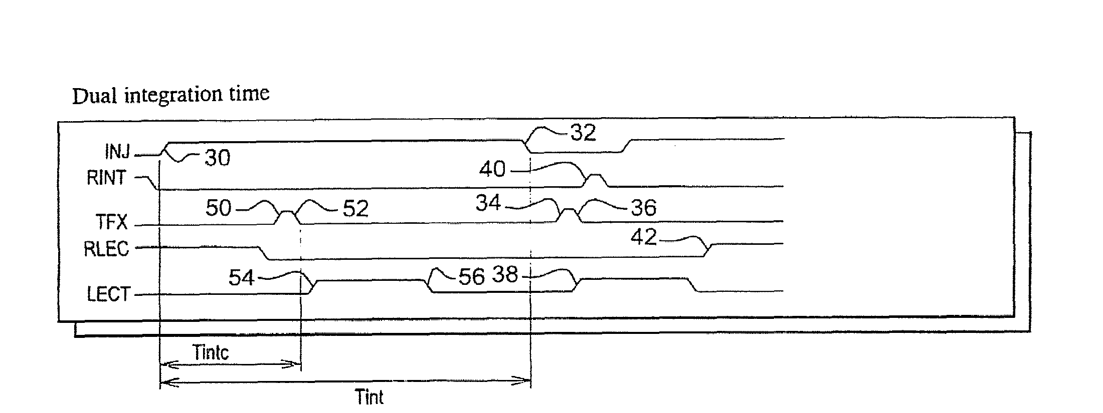
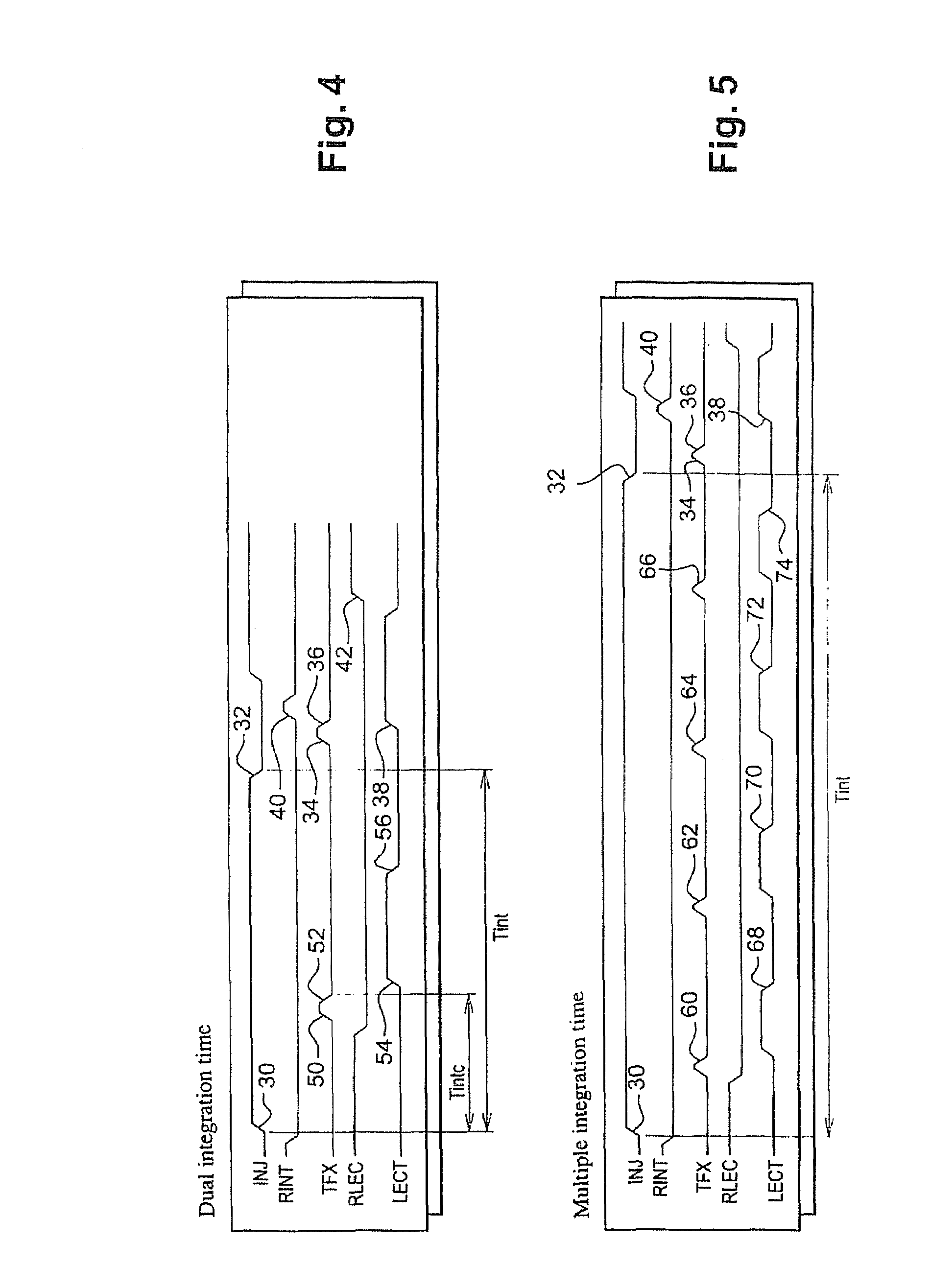
[0057]In FIG. 4, timing diagrams of control signals in the control circuit 24 show an inventive method of reading the electrical charges produced by the photodiode 12 employed by the read device 10 described in relation to FIG. 1.

[0058]This method mainly differs from the one described in relation to FIG. 2 in that the signal “TFX” is in addition switched, at 50, into its high state during the integration time Tint. The charges already stored in the integrating capacitor 14 are then transferred, via the switch 20, to the read capacitor 16. Once this almost instantaneous transfer is completed, the signal “TFX” is switched, at 52, into its low state. The read signal “LECT” is then switched, at 54, into its high state in order to read the voltage at the terminals of the read capacitor 16, and to transfer the read voltage to the outside of the device 10, and then switched, at 56, into its low state before the signal “INJ” is switched into its low state at 32.

[0059]Once the signal “INJ” i...


PUM


Abstract

A method of reading electrical charges produced by a photo-detector of a photo-detector matrix includes collecting and storing electrical charges produced by the photo-detector in a first capacitive element, transferring the charges stored in the first capacitive element to a second capacitive element, and reading the voltage at the terminals of the second capacitive element. The transfer followed by the reading is carried out in at least two phases: at least one first phase taking place during the collection and storage of the charges in the first capacitive element, and a second phase taking place at the end of the collection and storage of the electrical charges in the first capacitive element.

Description

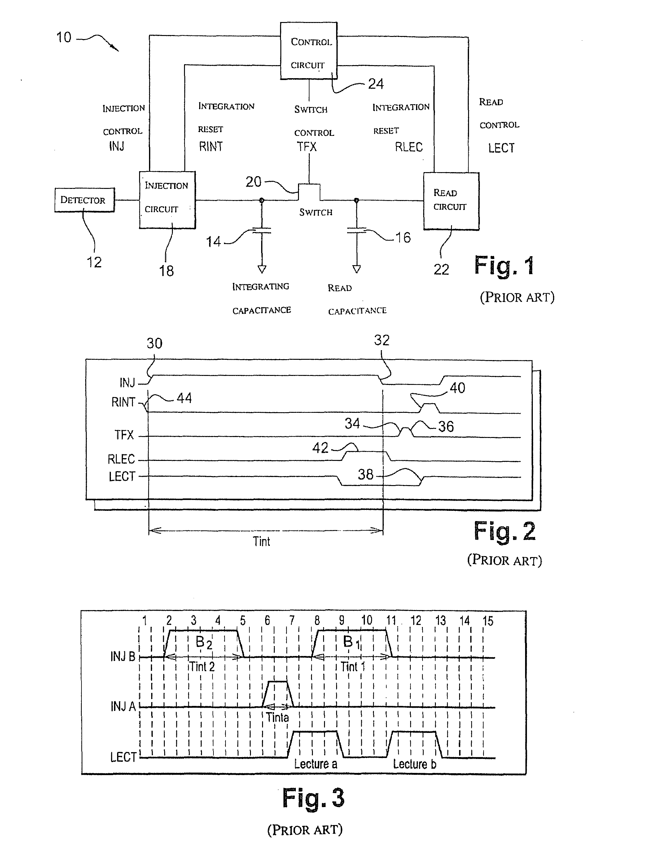
FIELD OF THE INVENTION[0001]The invention relates to the field of the reading of electrical charges created in elementary detectors of a matrix detector, and particularly photodiodes.PRIOR ART[0002]The use of elementary detectors, and particularly photodiodes, to detect electromagnetic radiation is known. Indeed, incident electromagnetic radiation on a photodiode in fact creates electrical charges therein. These charges are usually collected and accumulated in an integrating capacitance so that they can subsequently be read. This device is improved by allowing the integration and read phases to overlap in time. To this end, a reading capacitance and a transfer switch are usually used.[0003]FIG. 1 shows schematically, under the general reference 10, a prior art device of this kind for reading the electrical charges produced in a photodiode 12 belonging to a matrix of photodiodes in a detector of electromagnetic radiation, such as infrared radiation, visible radiation or ultra-violet ...

Claims


Application Information

Patent Timeline
Patent Type & Authority Applications(United States)
IPC IPC(8): G01J1/44H04N25/00
CPCG01J1/46H04N5/37452H04N5/35581H04N25/589H04N25/771
Inventor SANSON, ERIC
Owner DE DETECTEURS INFRAROUGES - SOFRADIR
Why Eureka
Eureka Blog
Learn More