
Vibration Based Damage Detection System

a technology of vibration-based damage detection and detection system, which is applied in vibration testing, structural/machine measurement, instruments, etc., can solve the problems of economic and environmental problems for industry stakeholders, severe impact on pipeline integrity, and dramatic impact on pipeline service li

Inactive Publication Date: 2010-04-15
DALHOUSIE UNIV
View PDF12 Cites 43 Cited by
  • Summary
  • Abstract
  • Description
  • Claims
  • Application Information

AI Technical Summary

Benefits of technology

[0015]The elements exemplary pipelines of this invention can function or embody any of the common elements described in the methods above. Furthermore, this novel damage detection method is useful for detecting damage in pipeline...

Problems solved by technology

Pipelines are critical transport elements, and their health and reliability through their designed service life are important issues for design and maintenance engineers.
Factors such as changes in the structural support due to ground shifting, aging, corrosion, impacts from heavy construction equipment, pressure cracks, thermal expansion and contraction, and defective welds can severely impact the integrity of pipelines and dramatically effect the service life of pipeline segments.
These factors can cause economical and environmental problems for industry stakeholders, including the producers, pipeline operators, regulatory agencies, the public, and others who are adversely effected by pipeline leakage.
Traditional methods for structural damage detection possess drawbacks such as the necessity of expensive equipment, poor sensitivity, and high labor costs, while other methods are not compatible with common structural pipeline materials such as plastic or metal.

Method used


Image

  • Vibration Based Damage Detection System
  • Vibration Based Damage Detection System
  • Vibration Based Damage Detection System

Examples


example 1

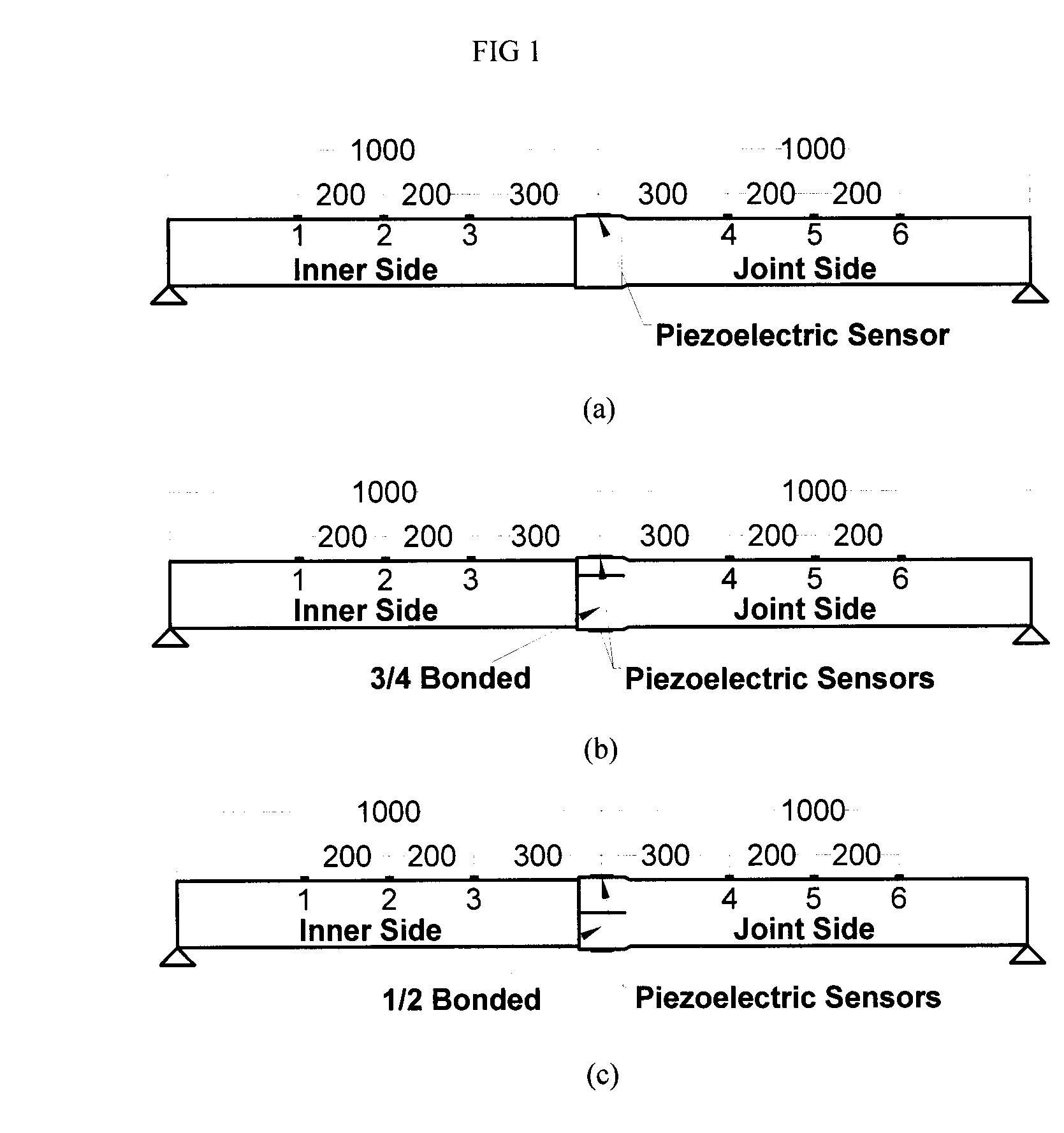
[0070]Referring FIG. 1, three different test specimens were used to demonstrate the present damage detection method. Three PVC pipe joints were prepared using IPEX 6 inch diameter PVC sewer pipes, with the dimensions shown in FIG. 1. The procedure used to prepare each of the bonded joints was as follows:

[0071]The pipe sections were cut to the appropriate length using a band saw;

[0072]The surfaces of the bonding regions were cleaned with isopropyl alcohol;

[0073]IPEX XIRTEC 7 primer was applied to the bonding regions;

[0074]IPEX XIRTEC 11 PVC cement was applied to the bonding regions;

[0075]The two sections of pipe were inserted into one another; and

[0076]The PVC cement was cured for a few minutes.

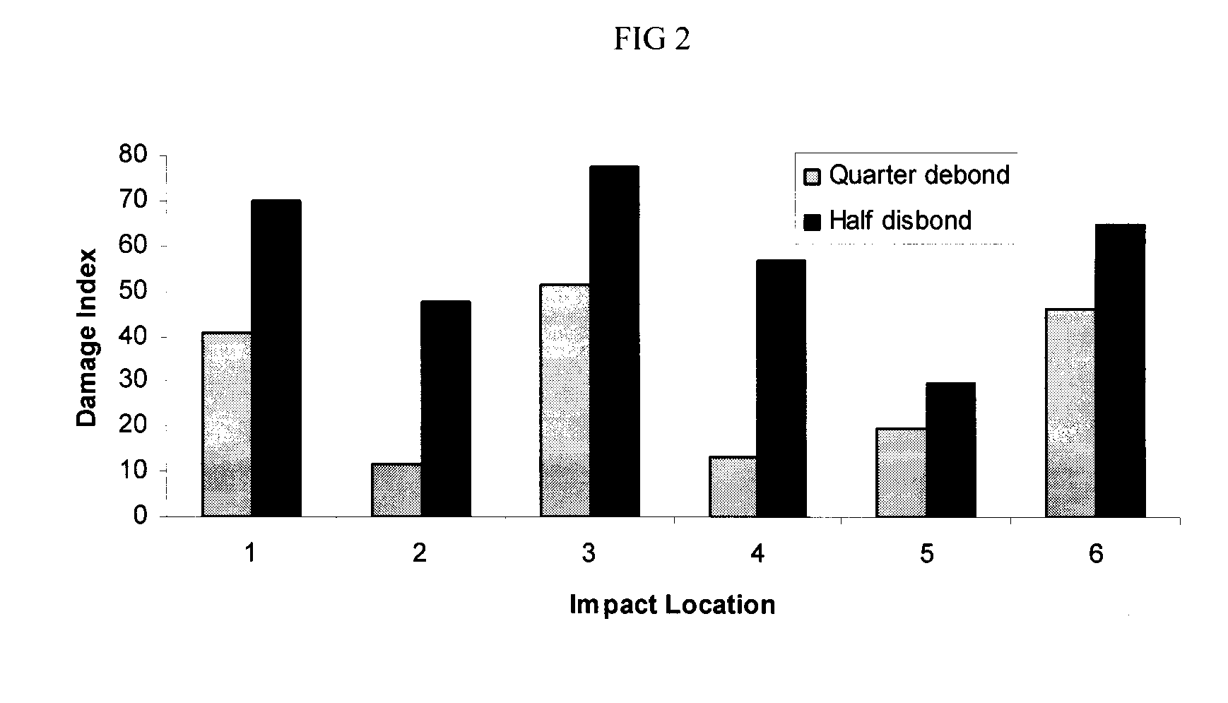
[0077]For the first test specimen, the joint is fully bonded around its entire circumference. For the second test specimen, the joint is bonded around approximately ¾ of the joint's circumference. In the third test specimen, the joint is bonded around approximately ½ of its circumference. See ...


PUM


Abstract

The present invention provides methods of assessing damage on a joint that includes energizing the joint, detecting the vibration of the joint using one or more signal generating sensors, processing the signal(s), and applying a damage index to the processed signal(s), wherein the damage index incorporates a processed control signal generated by a sensor(s) at or near the joint when the joint was healthy, i.e., in a substantially undamaged state. Another aspect of the present invention provides a pipeline that includes at least two pipe segments, at least one joint connecting the two pipe segments, and at least one signal generating sensor affixed to the pipeline that is capable of detecting vibration at or near the joint, at least one signal processor that is capable of EMD processing the signal, and an output device (e.g., computer monitor, LED display, a light bulb, an electronic alarm, or other sound or light generating device).

Description

CLAIM OF PRIORITY[0001]This application claims priority to U.S. provisional application Ser. No. 60 / 901,386, filed Feb. 15, 2007; and U.S. provisional application Ser. No. 60 / 932,506, filed May 31, 2007. The entire contents of each provisional application is hereby incorporated herein by reference in its entirety.FIELD OF THE INVENTION[0002]The present invention concerns vibration-based damage detection systems that are particularly useful for assessing damage to joints of pipes or other structures.BACKGROUND[0003]Vital resources such as oil, gas, water, and other fluid materials are transported through pipelines that span various terrains. Pipelines are critical transport elements, and their health and reliability through their designed service life are important issues for design and maintenance engineers. Factors such as changes in the structural support due to ground shifting, aging, corrosion, impacts from heavy construction equipment, pressure cracks, thermal expansion and con...

Claims


Application Information

Patent Timeline
IPC IPC(8): G01M7/02
CPCG01M7/025
Inventor TAHERI, FARID
Owner DALHOUSIE UNIV
Learn More