
Fixing unit and image forming apparatus having the same

a technology of fixing unit and image forming apparatus, which is applied in the direction of electrographic process apparatus, instruments, optics, etc., can solve the problems of inconvenient user configuration, creased print medium, speed printing, etc., and achieve the effect of simple structur

Inactive Publication Date: 2010-04-08
HEWLETT PACKARD DEV CO LP
View PDF3 Cites 14 Cited by
  • Summary
  • Abstract
  • Description
  • Claims
  • Application Information

AI Technical Summary

Benefits of technology

[0009]Accordingly, an aspect of the present invention is to process a fixing unit, which has a simple structure for adjusting the width of a fixing nip formed between a heating roller and a pressing roller to control pressure applied onto a print medium in the fixing nip according to characteristics of a printing job, and an image forming apparatus.
[0024]According to an aspect of the present invention, the one-way power transmission unit may allow the position-shift cam member to slip with regard to the driving shaft when the motor drives in the forward direction, and to rotate along with the driving shaft when the motor drives in the backward direction.

Problems solved by technology

Further, if the fixing nip with a pressure for the plain paper is used in the fix of the special paper, the print medium may be creased or the like.
However, this configuration is inconvenient for a user since he / she has to first manipulate the lever according to the kind of print medium.
However, this configuration is not suitable since the transport speed of the print medium has to be controlled during the printing job, and is also disadvantageous to high-speed printing.

Method used


Image

  • Fixing unit and image forming apparatus having the same
  • Fixing unit and image forming apparatus having the same
  • Fixing unit and image forming apparatus having the same

Examples


Embodiment Construction

[0036]Reference will now be made in detail to the present embodiments of the present invention, examples of which are illustrated in the accompanying drawings, wherein like reference numerals refer to the like elements throughout. The embodiments are described below in order to explain the present invention by referring to the figures.

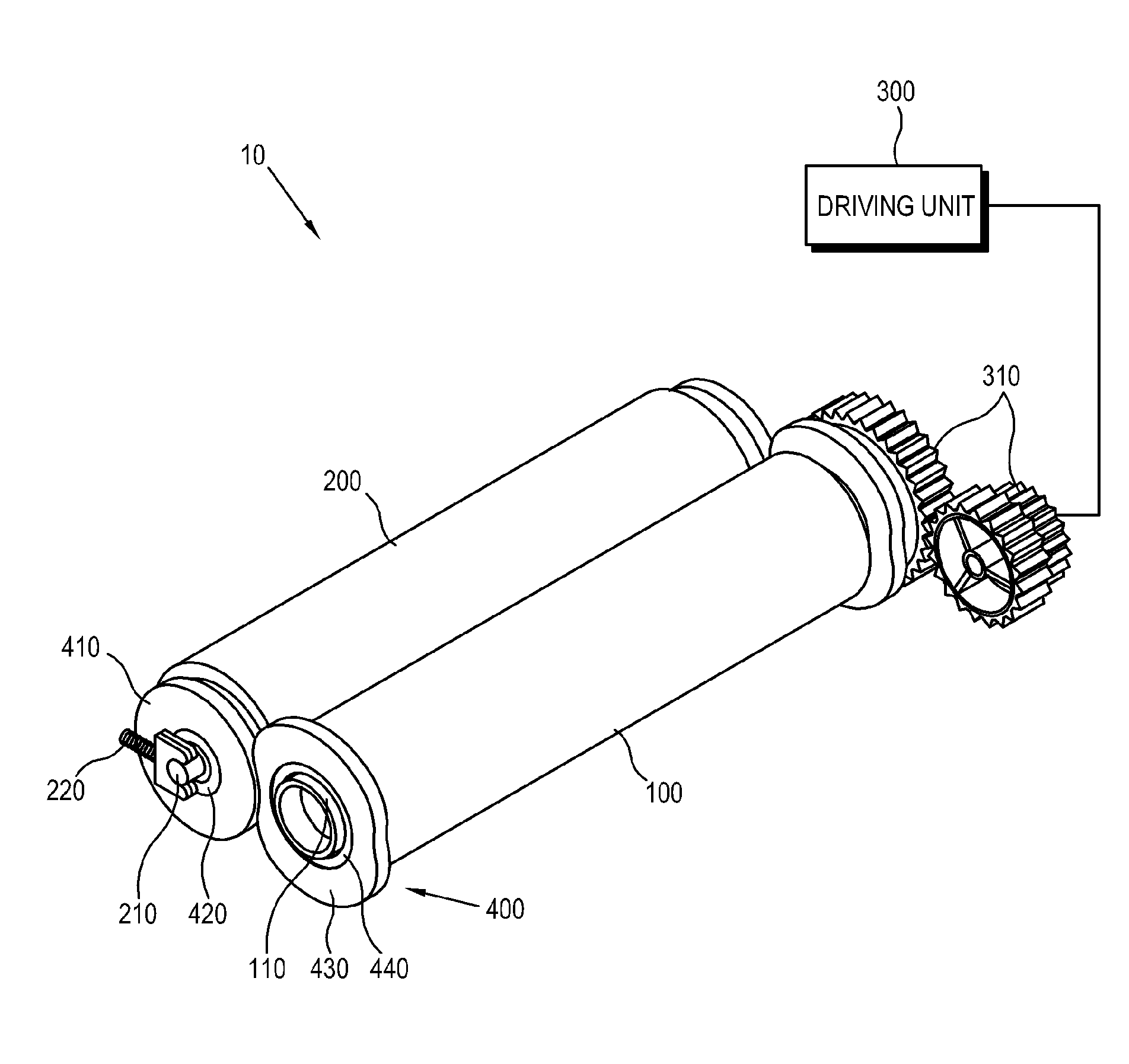
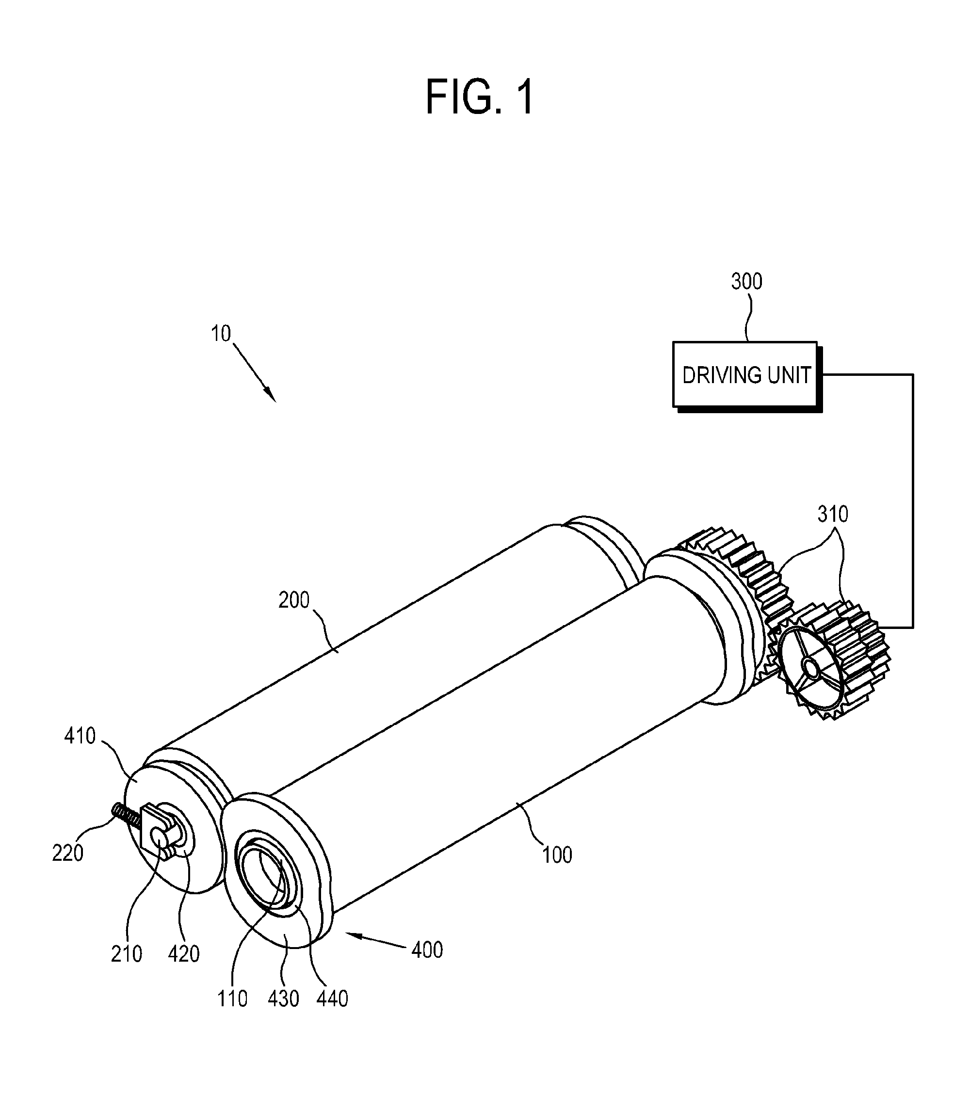
[0037]FIG. 1 is a perspective view of a fixing unit 10 of an image forming apparatus according to an exemplary embodiment of the present invention. When a visual image is formed by a developer on a print medium during a printing job, the fixing unit 10 applies heat and pressure to the print medium passing through the fixing nip, thereby fixing the visual image on the print medium.

[0038]As shown in FIG. 1, the fixing unit according to the present embodiment includes a heating roller 100 which generates heat, and a pressing roller 200 which presses against the heating roller 100 to form a fixing nip with the heating roller 100. A driving unit driver 300 ...


PUM


Abstract

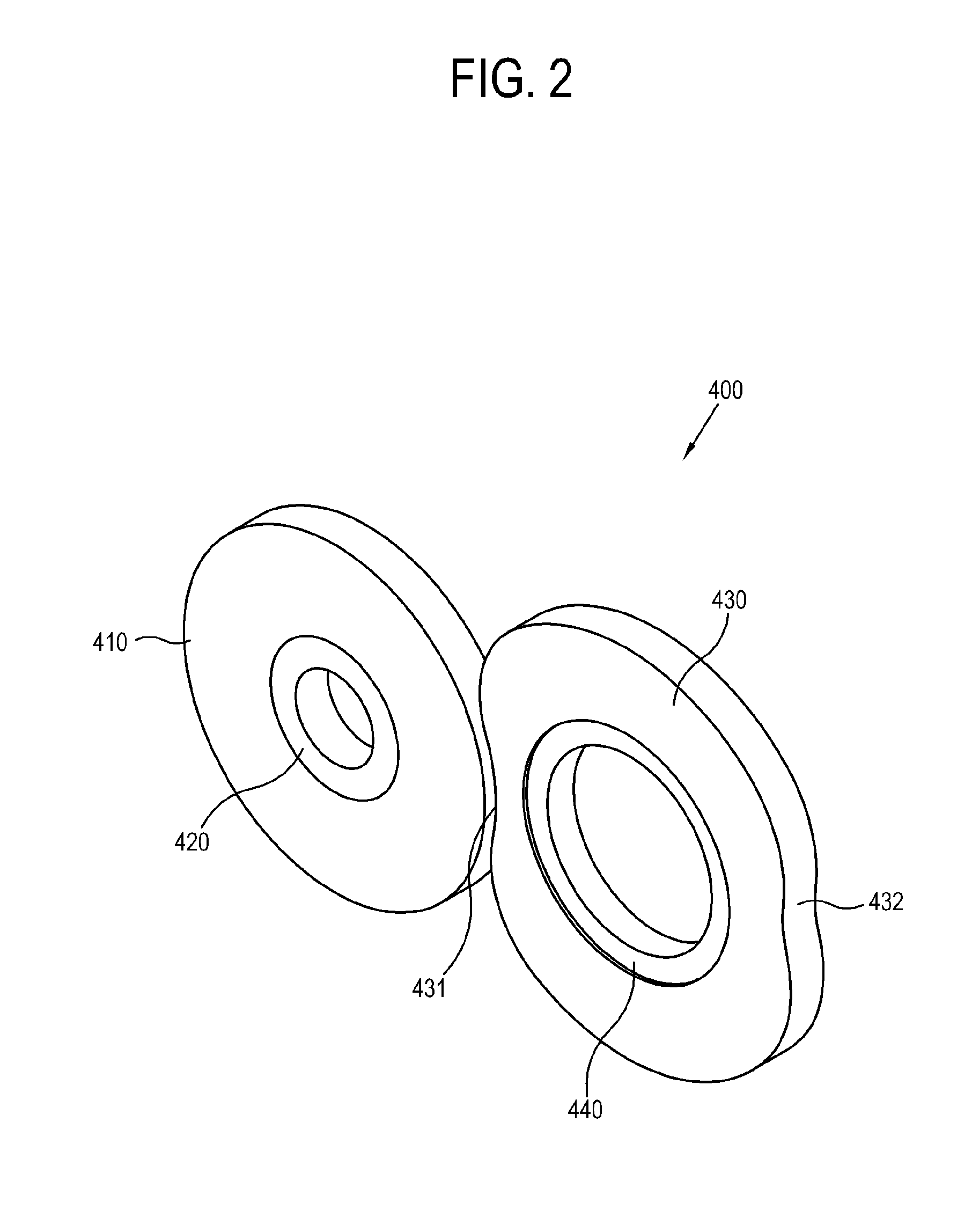
Disclosed is a fixing unit of an image forming apparatus, the fixing unit including a first roller; a second roller which forms a nip together with the first roller; and a nip adjuster which is provided in at least one end part of the first roller and includes a restrictive ring formed with a plurality of cam profiles for regulating an axis distance between the first roller and the second roller to be varied to adjust a width of the nip.

Description

CROSS-REFERENCE TO RELATED APPLICATION[0001]This application claims the benefit of Korean Patent Application No. 2008-98710, filed Oct. 8, 2008 in the Korean Intellectual Property Office, the disclosure of which is incorporated herein by reference.BACKGROUND OF THE INVENTION[0002]1. Field of the Invention[0003]Apparatuses and methods consistent with aspects of the present invention relate to a fixing unit for fixing an image on a print medium and an image forming apparatus having the same, and more particularly, to a fixing unit capable of adjusting the width of a fixing nip according to characteristics of a printing job and an image forming apparatus having the same.[0004]2. Description of the Related Art[0005]An image forming apparatus uses a developer (such as ink or a toner) to form a visual image on a print medium. An electrophotography-type image forming apparatus forms an electrostatic latent image due to an electric potential difference on an image carrying body, applies a d...

Claims


Application Information

Patent Timeline
IPC IPC(8): G03G15/20
CPCG03G15/2032G03G15/2064G03G2215/2025
Inventor KIM, HAN-KYOO
Owner HEWLETT PACKARD DEV CO LP
Learn More