
Detecting Method for Touch Panel

a detection method and touch panel technology, applied in the field of touch panel detection methods, can solve the problems of resistive touch panel not being able to process multiple touch inputs or perform fingerprint recognition, resistive touch panel subject to the limitation of minimum applied force, slow gradient image processing method, etc., and achieve the effect of saving data storage spa

Active Publication Date: 2010-04-01
AU OPTRONICS CORP
View PDF8 Cites 31 Cited by
  • Summary
  • Abstract
  • Description
  • Claims
  • Application Information

AI Technical Summary

Benefits of technology

[0007]It is an object of the present invention to provide a detecting method for a touch panel to save the data storage space.
[0008]It is another object of the present invention to provide a detecting method for a touch panel to improve the system efficiency.
[0009]It is yet another object of the present invention to provide a detecting method for a touch panel to increase the response speed of the touch panel.
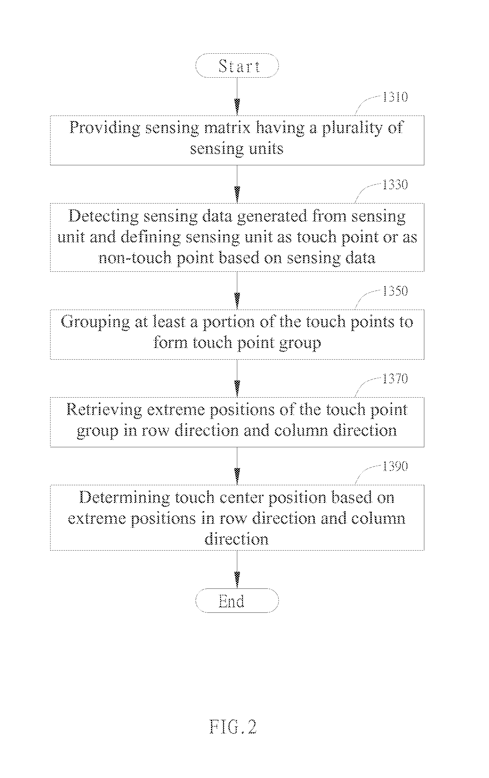
[0010]The detecting method of the present invention includes firstly providing a sensing matrix having a plurality of sensing units. When the sensing unit is touched, the sensing element of the sensing unit will detect a signal variation generated and determine the location of the sensing unit which generates the signal variation. The detecting method includes detecting sensing data generated from each of the sensing units to determine the sensing unit as a touch point or as a non-touch point. At least a portion of the touch points are grouped into a touch point group. The projection of each touch point in the touch point group is overlapping a projection of at least one of the rest touch points of the touch point group in one of a row direction or a column direction and is adjacent to a projection of at least one of the rest touch points of the touch point group in the other direction. More than one touch point groups may occur simultaneously in the sensing matrix within the same sensing period and this gives the touch panel multi-touch function.

Problems solved by technology

However, the resistive touch panel cannot process multiple touch inputs or perform fingerprint recognition.
Furthermore, the user needs to apply certain amount of pressure on the touch point to create a conduction loop, thus the resistive touch panel is subjected to the limitation of minimum applied force.
However, the gradient image processing method is slow and requires a large amount of storage space which in turn decreases the overall system efficiency.

Method used


Image

  • Detecting Method for Touch Panel
  • Detecting Method for Touch Panel
  • Detecting Method for Touch Panel

Examples


Embodiment Construction

[0021]The present invention provides a detecting method for a touch panel. In preferred embodiments, the detecting method of the present invention is applied to an optical touch panel. However, in different embodiments, the detecting method of the present invention can be applied to capacitive touch panels, inductive touch panels, resistive touch panels, or other touch panels with multi-touch function.

[0022]FIG. 1 is a schematic view of the touch panel. As FIG. 1 shows, the touch panel includes a plurality of sensing units 101. In a preferred embodiment, the sensing units 101 represent unit areas obtained by dividing the touch panel. The sensing units 101 are preferably arranged to form a sensing matrix 110, wherein the sensing matrix 110 has a plurality of parallel sensing row 130. Each of the sensing rows 130 includes a plurality of the sensing units 101 distributed in a straight line. Take a 16×16 sensing matrix 110 for instance; the sensing matrix 110 has sixteen sensing rows 13...


PUM


Abstract

This invention provides a detecting method for a touch panel, comprising providing a sensing matrix having a plurality of sensing units, detecting sensing data generated from the sensing unit and defining the sensing unit as a touch point or a non-touch point based on the sensing data and group at least a portion of the touch points to form a touch point group. In the same touch point group, projection of a touch point overlaps a projection of at least one touch point of the touch point group in one of a row direction and a column direction while adjacent to a projection in the other direction of at least one touch point of the touch point group. Afterward, extreme positions of the touch point group in the row direction and the column direction is retrieved. Lastly, the detecting method includes determining a touch center position based on the extreme positions in the row direction and the column direction.

Description

BACKGROUND OF THE INVENTION[0001]1. Field of the Invention[0002]This invention relates to a detecting method for a touch panel.[0003]2. Description of the Prior Art[0004]Flat display devices have become the mainstream in various types of display devices. For instance, the home televisions, monitors of personal computers and laptop computers, mobile phones, and display cameras are electronic products which extensively incorporate the flat display devices. As product design is driven toward user friendliness, thus display panels having touch input function are gradually becoming a key aspect in the development of flat display device industry.[0005]Conventional touch panel technologies include resistive type, capacitive type and optical type touch panels. As for the resistive touch panels, the working principle is to determine a touch point by detecting voltage drops on the touch panel. The resistive touch panel includes two conductive layers separated by a narrow gap and a voltage dif...

Claims


Application Information

Patent Timeline
IPC IPC(8): G06F3/041
CPCG06F3/0416G06F3/04166
Inventor YANG, CHUN-WEIHSU, YU-MIN
Owner AU OPTRONICS CORP
Learn More