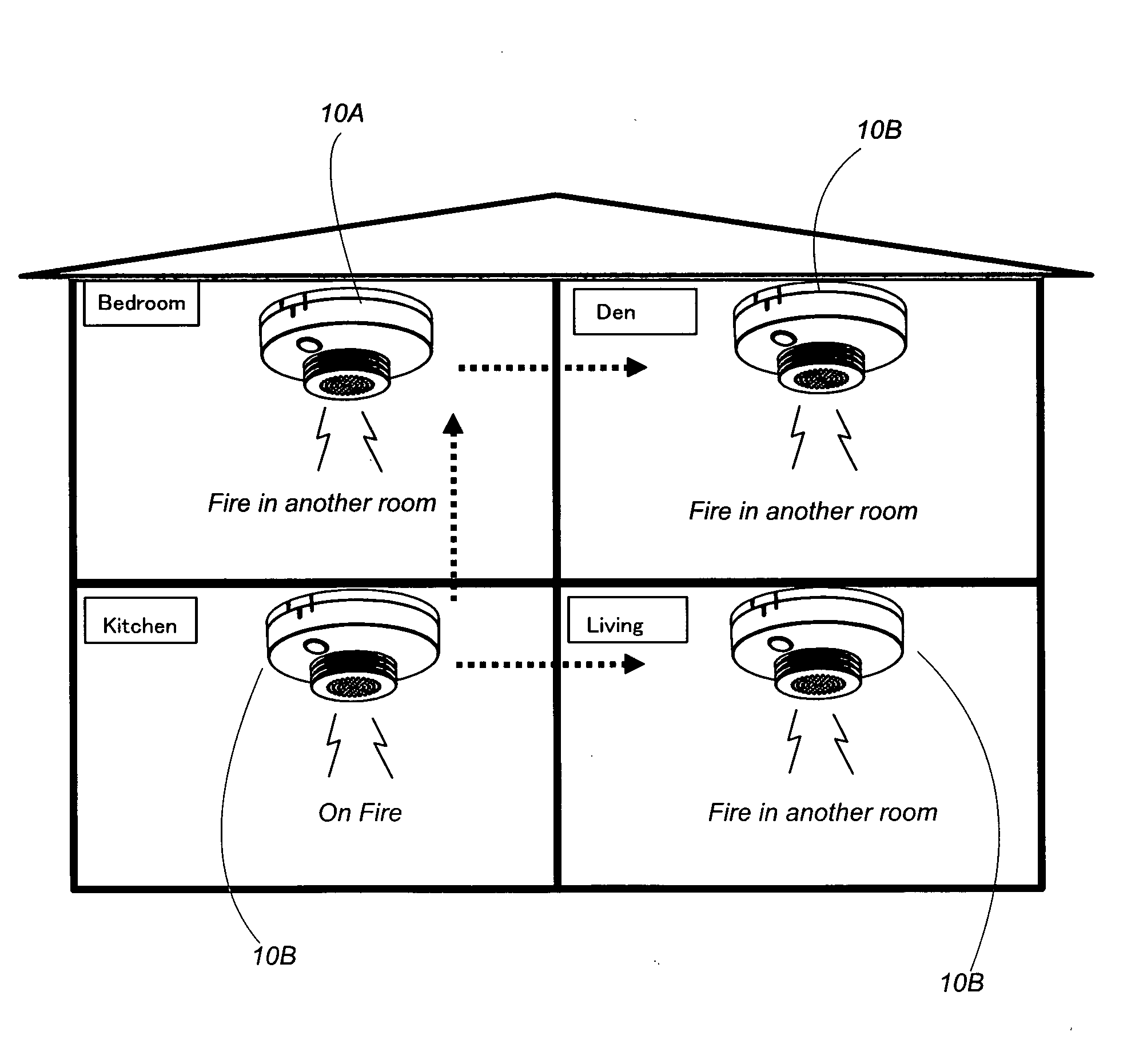
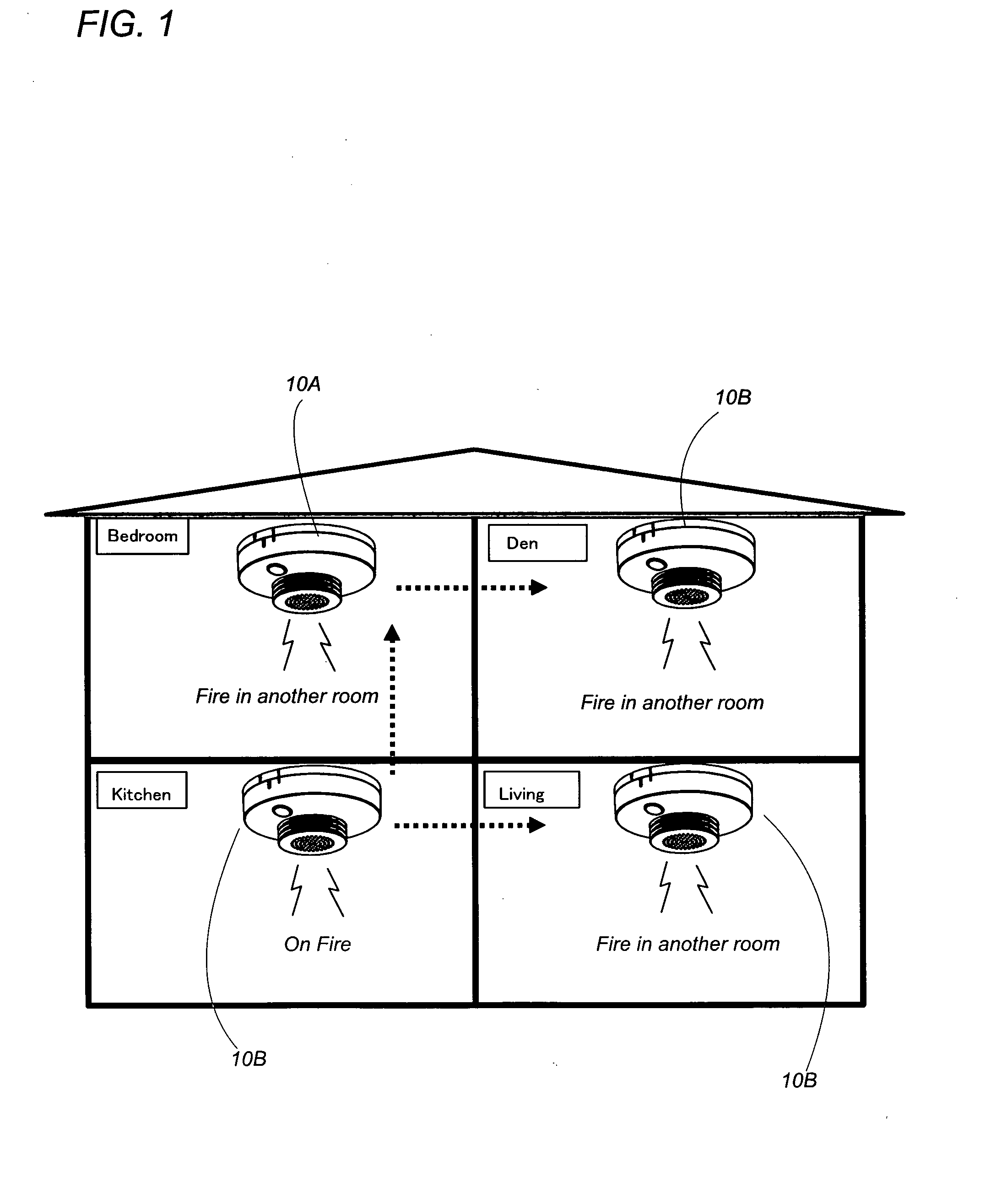
[0004]Each of the fire detecting terminals is composed of a second battery (14B) energizing the fire detecting terminal, a fire sensor (12B) configured to detect a fire condition, a second information generator (30B) configured to generate the
fire detection message upon detection of the fire condition, a second
transmitter (40B) configured to transmit the
fire detection message, a second
receiver (40B) configured to receive the fire detection message and the fire information message, and an
alarm device (50B) configured to issue a fire alarm upon receiving the fire detection message or the fire information message. The fire detecting terminal includes a
power controller (60B) which is configured to selectively provide an intermittent reception mode of activating the second
receiver (20B) in a limited reception period alternating with a
rest period, and a constant reception mode of constantly keeping the second receiver ready for receiving the fire information message. The second
power controller (60B) is configured to select the intermittent reception mode until receiving the fire detection message, and select the constant reception mode thereafter to receive the fire information message for establishing the multiple synchronous communication by way of the timeslots. With this arrangement, the fire detecting terminals can be activated only intermittently until receiving the information of true fire occurrence, thereby reducing a
power consumption of the battery for a prolonged battery life, yet assuring to make the multiple synchronous communication between the master station and the fire detecting terminals successfully after acknowledging the fire occurrence for reliable
information exchange.
[0005]Preferably, the first information generator (30A) of the master station (10A) is configured to generate a wake-up message after receiving the fire detection message from any one of the fire detecting terminals. The wake-up message is configured to be destined for all the fire detecting terminals. In this instance, the first
transmitter (40A) of the master station is configured to transmit the wake-up message repeatedly over a predetermined period before transmitting the fire information message in order to wake-up the fire detecting terminals from the intermittent reception mode. The second power controller (60B) of each fire detecting terminal (10B) is configured to select the constant reception mode upon receiving the wake-up message from the master station (10A) and the fire detection message from anyone of the fire detecting terminals whichever comes earlier, thereby making the second receiver ready for the multiple synchronous communication with the master station commenced by the fire information message. Thus, all the fire detecting terminals can be activated by the wake-up
signal from the master station for successfully starting the multiple synchronous communication with the master station, even if the fire detecting message from one of the fire detecting terminals fails to wake-up one or more of the other fire detecting terminals.
[0007]Also in this connection, the
alarm device (50B) of each fire detecting terminal (10B) is configured to issue the fire alarm upon receiving the wake-up message or the fire detection message whichever comes earlier. Thus, all the fire detecting terminals can successfully give the fire alarm before starting the multiple synchronous communication for prompt attention to residents.
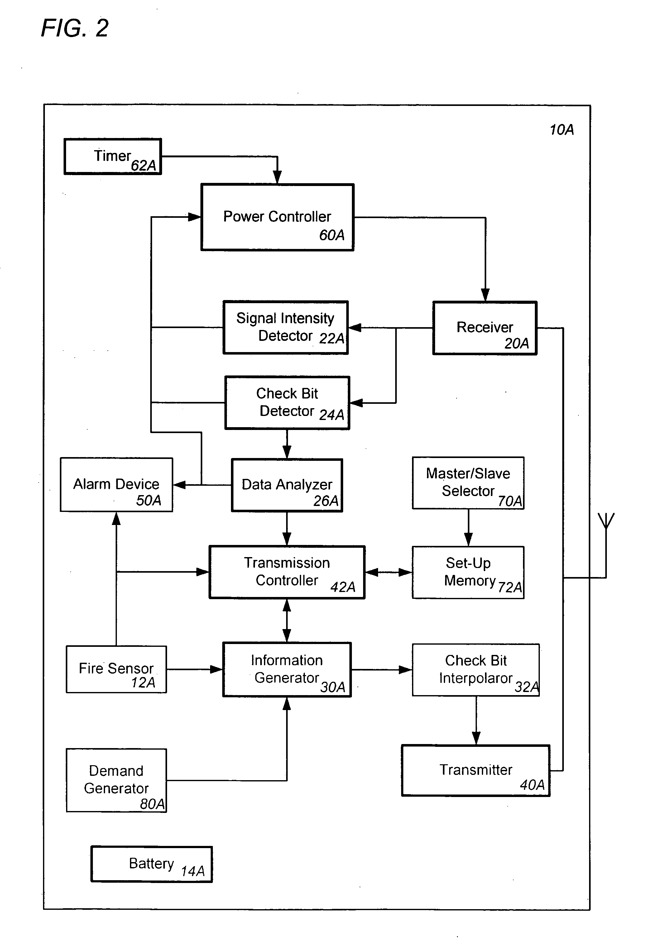
[0011]In the present invention, the master station can be also powered by an incorporated battery (12A), and include a first power controller (60A) configured to selectively provide an intermittent reception mode of activating the first receiver (20A) in a limited reception mode alternating with a
rest period, and a constant reception mode of constantly keeping the first receiver (20A) ready for receiving the fire information message. Like the second power controller of the fire detecting terminal, the first power controller (60A) is configured to select the intermittent reception mode until receiving the fire detection message from anyone of the fire detecting terminals, and thereafter select a waking-up mode of transmitting the wake-up message repeatedly for a limited number of times and the subsequently select the constant reception mode of transmitting the fire information message for starting the multiple synchronous communication with the fire detection terminals. Thus, the battery-powered master station can be also power-saved for prolonged operation life of the system.
[0012]The master station may include an
alarm device configured to issue a fire alarm upon receiving the fire detection message for giving the fire alarm also in
a site where the master station is installed. Further, the master station can be equipped with a fire sensor (12A) and the first information generator (30A) configured to generate the fire detection message to be transmitted to each of the fire detecting terminals (10B) as well as the fire information message upon receiving the fire condition from the fire sensor. Thus, the master station can share the function of the fire detecting terminals to improve system versatility.


