
Laser assisted drilling

a laser and assisted drilling technology, applied in the direction of other manufacturing equipment/tools, manufacturing tools, welding/soldering/cutting articles, etc., can solve the problems of less effective force when drilling non-vertically, less effective when using a more flexible drill string, and high cost of tractor systems, so as to facilitate the use of coiled tubing

Inactive Publication Date: 2010-04-01
GAS TECH INST
View PDF28 Cites 98 Cited by
  • Summary
  • Abstract
  • Description
  • Claims
  • Application Information

AI Technical Summary

Benefits of technology

[0009]It is one object of this invention to provide an apparatus for facilitating the use of coiled tubing in the underground drilling of boreholes.
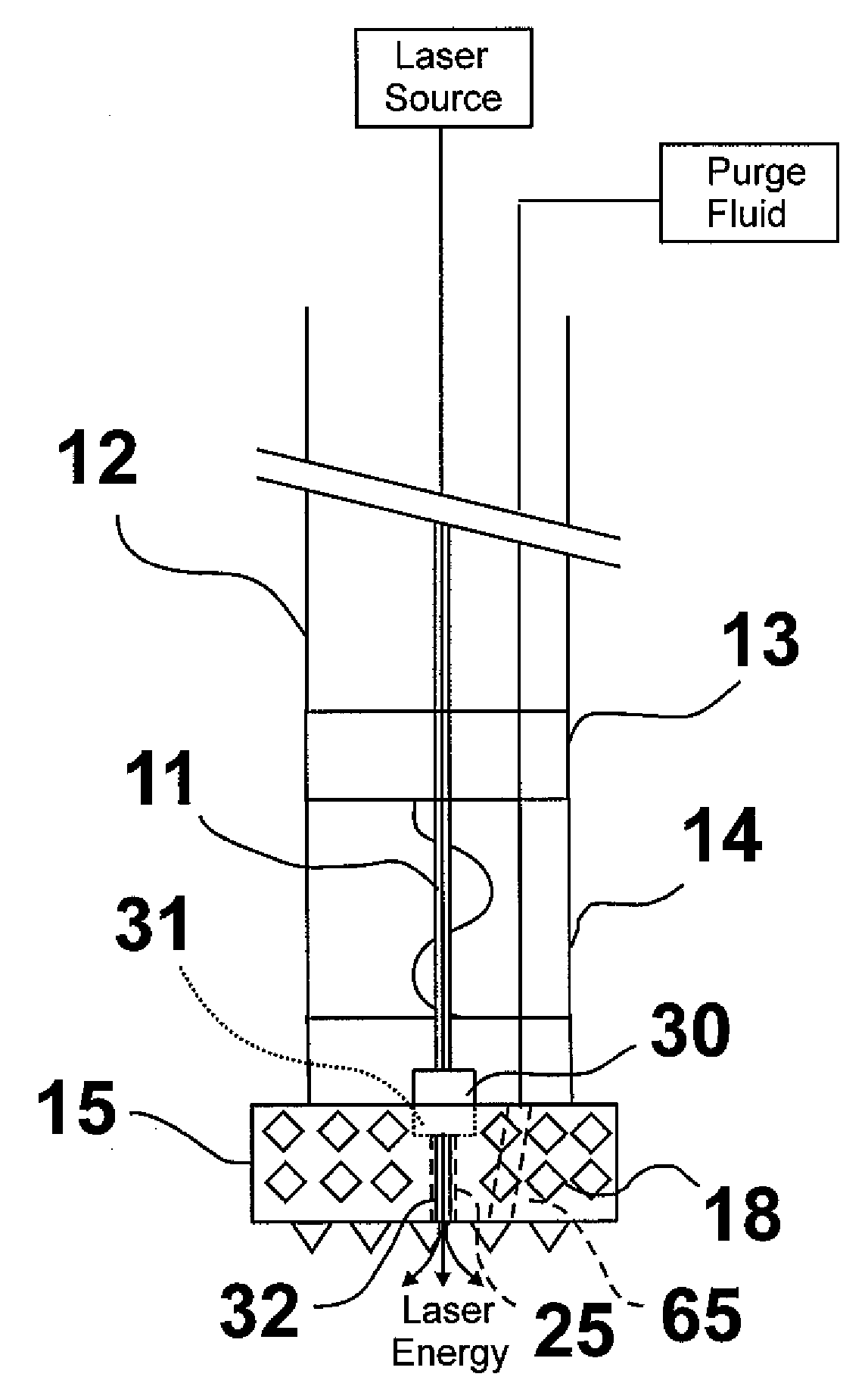
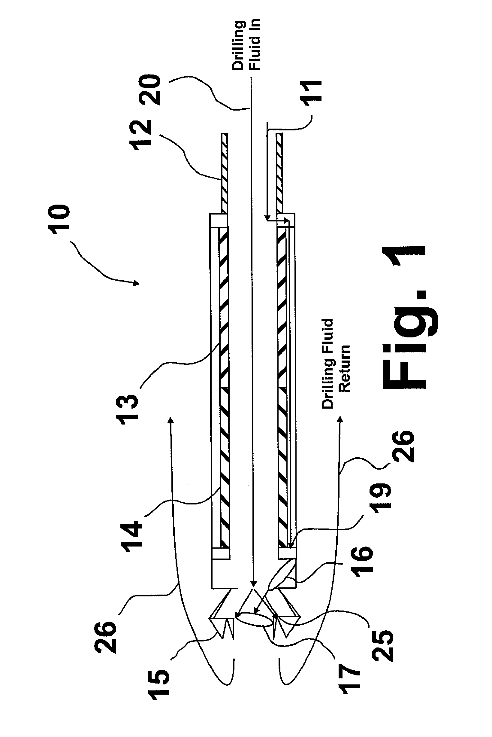
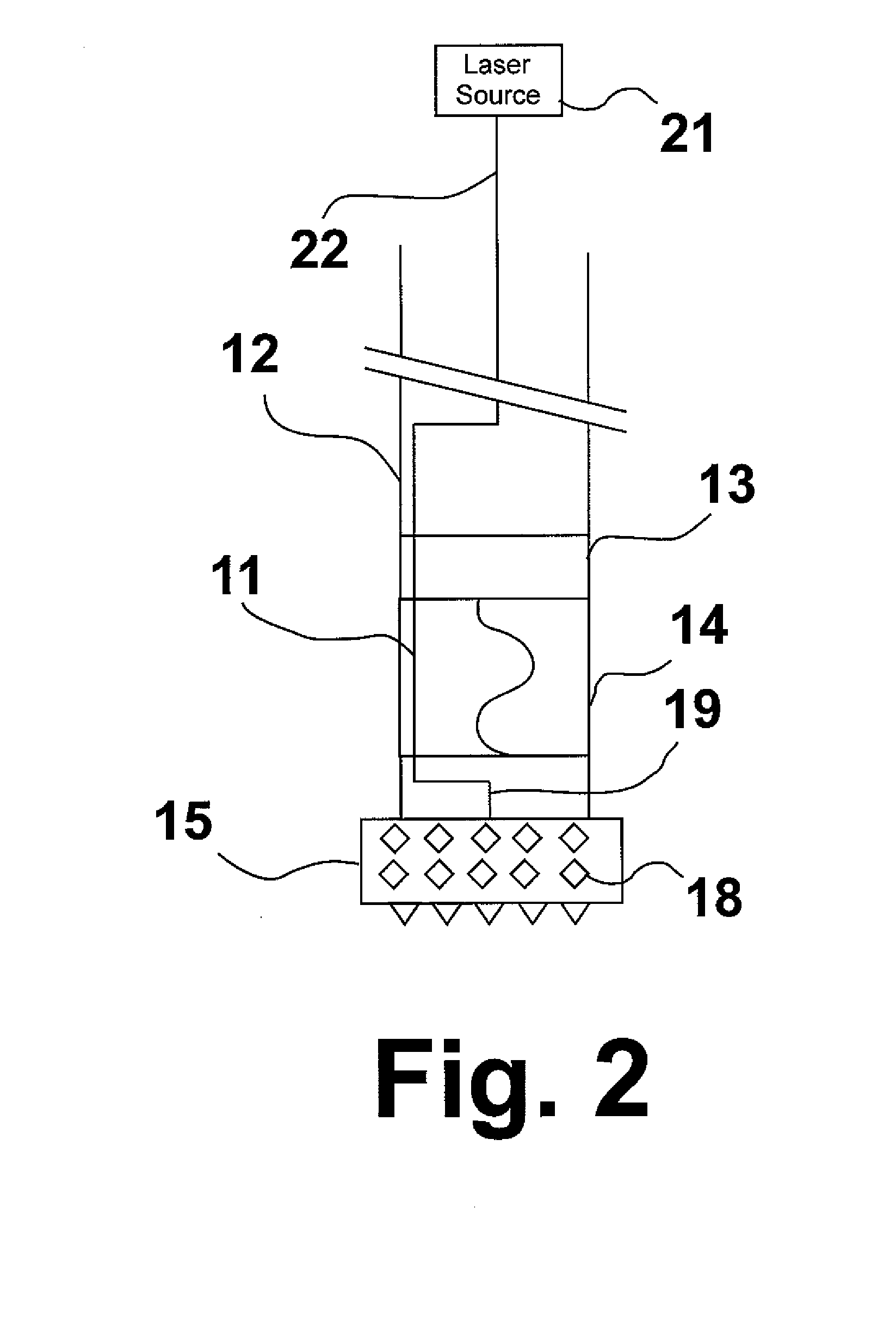
[0012]These and other objects of this invention are addressed by an apparatus for drilling underground comprising at least one optical fiber for transmitting light energy from a laser energy source to an underground drilling location and a mechanical drill bit having at least one cutting surface and forming at least one light transmission channel aligned to transmit light from the at least one optical fiber through the mechanical drill bit by way of the at least one light transmission channel. This invention can increase the speed and / or efficiency of drilling systems for drilling holes in substances such as concrete, granite, limestone, sandstone, and other rock materials; it can be used for a wide range of drilling operations in substances such as concrete, cement, rock, limestone, marble, quartz, etc.; and it is especially suitable for drilling horizontal boreholes in the ground for producing and recovering oil, gas, water, and geothermal energy. This invention may also be used for drilling smaller holes for logging, for side tracking through existing holes or with reaming bits. It may be used to drill boreholes of a variety of sizes but is especially suitable for drilling holes in the range of about 0.5 inches to about 20 inches in diameter.

Problems solved by technology

However, this method of force becomes less effective when drilling non-vertically, i.e. curved holes, side tracking or horizontal drilling, and even less effective when using a more flexible drill string such as coiled tubing, most notably when drilling in very hard materials such as granite.
Although effective in many applications, the tractor systems are very expensive and have difficulties maneuvering through softer formations where the surface breaks down and is not able to provide the requisite anchoring.

Method used


Image

  • Laser assisted drilling
  • Laser assisted drilling
  • Laser assisted drilling

Examples


Embodiment Construction

[0026]The invention disclosed herein is a laser assisted drilling system for underground drilling, which includes a laser assisted mechanical drill bit and optical fibers for the transmission of laser energy from a laser source disposed above ground or within the drill string to the drill bit. The advantages of this invention compared with conventional technologies include an increase in drilling speed due to the use of laser energy to spall ahead of the mechanical drill bit the material ahead of the mechanical drill bit being drilled prior to utilization of the mechanical drill bit; the ability to use the laser energy on demand to selectively soften the material only when needed; the ability to use smaller diameter and thinner wall drill strings due to the reduced force on the drill bit, more control over the direction of the drilling, and less tendency of the drill string to buckle, especially with respect to flexible drill strings such as coiled tubing; the ability to provide add...


PUM

PropertyMeasurementUnit
Angleaaaaaaaaaa
Lengthaaaaaaaaaa
Transmissionaaaaaaaaaa

Abstract

An apparatus for drilling underground having at least one optical fiber for transmitting light energy from a laser energy source disposed above ground to an underground drilling location and a mechanical drill bit having at least one cutting surface and forming at least one light transmission channel aligned to transmit light from the at least one optical fiber through the mechanical drill bit by way of the at least one light transmission channel.

Description

BACKGROUND OF THE INVENTION[0001]1. Field of the Invention[0002]This invention relates to underground drilling methods and apparatuses. In one aspect, this invention relates to non-vertical drilling methods and apparatuses for drilling non-vertical boreholes. In one aspect, this invention relates to the use of lasers as a means for augmenting the mechanical drilling process. In another aspect, this invention relates to the use of lasers as a means for augmenting the functionality of a mechanical drill bit used in drilling underground. In yet another aspect, this invention relates to the use of lasers as a means for facilitating the use of coiled tubing for drilling underground. In yet another aspect, this invention relates to use of laser as a means for cleaning the walls of drilled wells and removing formation damage from drilling fluid.[0003]2. Description of Related Art[0004]Conventional underground drilling is typically carried out using a rotary drill bit attached to a drill st...

Claims


Application Information

Patent Timeline
IPC IPC(8): B23K26/14E21B7/15
CPCB23K26/106B23K26/381B23K26/4075B23K2201/20E21B7/15B23K2201/002B23K26/382B23K26/40B23K2101/002B23K2101/20B23K2103/50
Inventor PERRY, KENTSALEHI, IRAJABBASI, HAMID A.
Owner GAS TECH INST
Learn More