Eureka AIR delivers breakthrough ideas for toughest innovation challenges, trusted by R&D personnel around the world.

High flash point additives for treating carbon-based fuels

a technology of additives and carbon-based fuels, applied in the direction of biofuels, fuels, waste-based fuels, etc., can solve the problem of dangerous vapors, and achieve the effects of high boiling point solvent, lower flash point, and high flash point materials

Inactive Publication Date: 2010-04-01
LIQUID MINERALS GRP LTD
View PDF2 Cites 36 Cited by
  • Summary
  • Abstract
  • Description
  • Claims
  • Application Information

AI Technical Summary

Benefits of technology

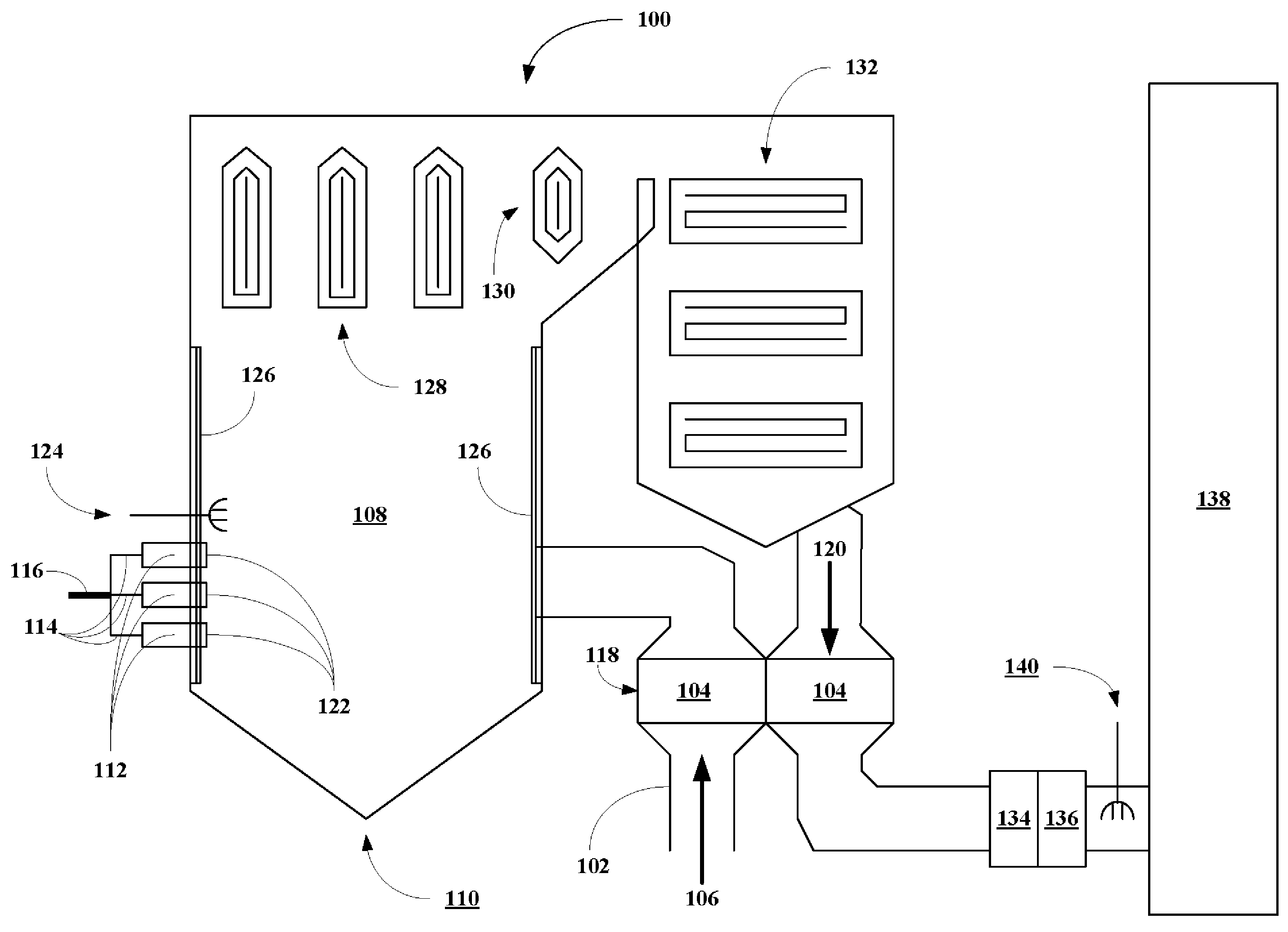
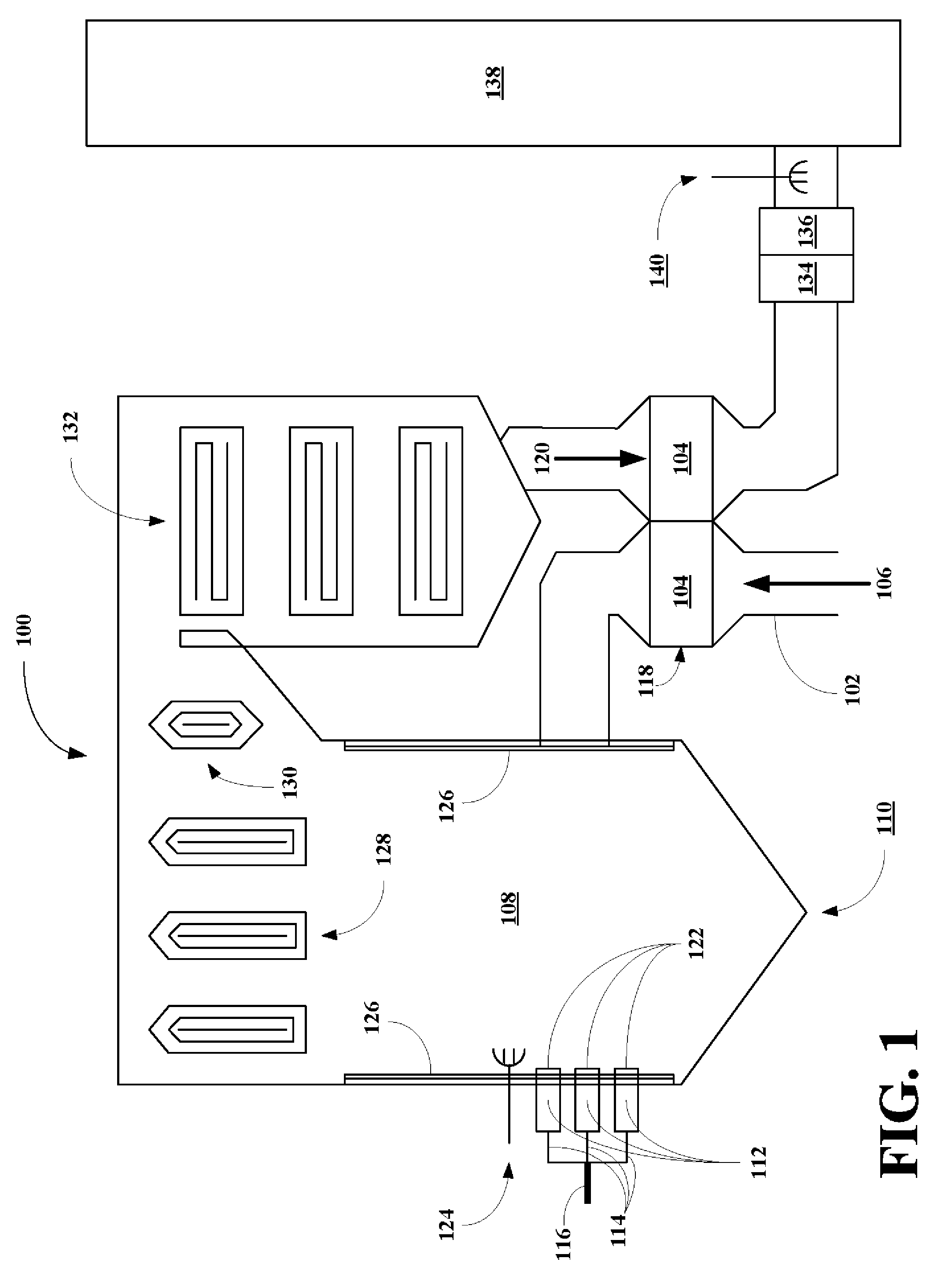
[0034]The present invention also provides safer high flash point products for use in coal fired boilers or other types of combustion equipment. Since coal fired boilers or any other combustion equipment in which the invention may be used operate at high temperatures, it is important to maintain the highest possible flash point of the combustible materials to avoid or otherwise minimize the danger from fires. Flash point is directly related to vapor pressure of the products. The higher the flash point, the lower the expected vapor pressure of the materials and vice versa. Thus, even if there were a spill or leak, the use of higher flash point products would not result in high solvent vapor pressures. Such vapors can be dangerous as they potentially could travel over distances to where a spark or flame could ignite the vapors. Combustion relies upon fuel, oxygen, and temperature. By minimizing the vapor concentration we are reducing the fuel source. This makes the products of this invention inherently safer to use in the potentially dangerous environments.
[0035]The present invention provides a method for conveniently producing fuel products having high flash points.

Problems solved by technology

Such vapors can be dangerous as they potentially could travel over distances to where a spark or flame could ignite the vapors.

Method used


Image

  • High flash point additives for treating carbon-based fuels
  • High flash point additives for treating carbon-based fuels
  • High flash point additives for treating carbon-based fuels

Examples


example 1

[0057]A suitably sized three neck reaction flask was fitted with stirrer, thermometer, heating source, and condenser system. To this were added first 100 grams of a high boiling solvent such as Calsol 100, 200 grams of a low boiling solvent, and 115 grams of oleic acid. To this stirred solution were then slowly added 472 grams of magnesium hydroxide. Not all of the magnesium hydroxide will necessarily dissolved at low temperatures, but the magnesium hydroxide should be well dispersed. Heat was then applied to just remove the 200 grams of the low boiling solvent and any water that is formed during the reaction of the magnesium hydroxide and the high boiling solvent and oleic acid and processing. Typically the temperature will need to be raised to about 400° C., but no less than 350° C. Upon cooling, a sufficient amount of the high flash point solvent was added (generally, about 100 grams of Calpar 325) to reduce the magnesium content to about 30.0 wt. %. Upon cooling, about 641 grams...

example 2

[0058]A standard formulation for a nanoparticle magnesium overbase compound was followed. Following the normal dilution the flash point was measured. It was 65° C. using a Pensky Martens Closed Cup method (ASTM D-93). This material had the standard properties associated with this additive.

example 3

[0059]Another standard formulation for a nanoparticle magnesium overbase compound was followed. However, in this case the normal dilution solvent was not used. Instead additional quantities of the high flash point solvent was used. The flash point in this case was increased to 160° C., using again the Pensky Martens Closed Cup method. Most of the standard properties of this material were seen with only a minor increase in product viscosity, still within specifications.


PUM

PropertyMeasurementUnit
particle sizeaaaaaaaaaa

Abstract

A simple method is disclosed to produce oil soluble nano particle size additives with significantly higher flash points to improve the safety aspects of these products especially when used in, around, and near high temperature combustion equipment.

Description

BACKGROUND OF THE INVENTION[0001]1. Field of the Invention[0002]The present invention relates generally to a high flash point composition and a safe method for treating fuel-burning boilers to control emissions and deposits.[0003]More particularly, a high flash point composition and a safe method for treating fuel-burning boilers to control emissions, where the composition comprises a high flash point liquid including oil-soluble nano-particle size additive particles for fuel such as coal to reduce emissions and deposits.[0004]2. Description of the Related Art[0005]In the generation of electricity the often preferred fuel is natural gas. Natural gas is preferred because it contains very few if any contaminants. Contaminants often cause problems in the power generating industry. Some of these problems result from deposits that accumulate on heat transfer surfaces in boilers, the moving blades in gas turbines, or the moving pistons and valves in diesel engines. These deposits reduce t...

Claims


Application Information

Patent Timeline
Patent Type & Authority Applications(United States)
IPC IPC(8): C10L1/12
CPCB01J13/0026C10L1/10C10L1/1233C10L1/1616C10L1/1881C10L5/04Y02E50/30C10L5/445C10L5/447C10L10/00C10L10/02Y02E50/10C10L5/442
Inventor HUGHES, MARK D.SMITH, DANIEL T.KOCH, KENNETH W.SMOTER, NATHANIEL
Owner LIQUID MINERALS GRP LTD
Why Eureka
Eureka Blog
Learn More