Photovoltaic integrated variable frequency drive

a variable frequency drive and photovoltaic technology, applied in power conversion systems, circuit arrangements, ac-ac conversion, etc., can solve problems such as multifunctional applications, and achieve the effects of facilitating bi-directional power flow, bi-directional power flow, and bi-directional power flow

Inactive Publication Date: 2010-03-25
ELECTRIC POWER RES INST INC
View PDF3 Cites 47 Cited by
  • Summary
  • Abstract
  • Description
  • Claims
  • Application Information

AI Technical Summary

Problems solved by technology

Unfortunately, these applications are not multifunctional and use PV as the only source.

Method used


Image

  • Photovoltaic integrated variable frequency drive
  • Photovoltaic integrated variable frequency drive
  • Photovoltaic integrated variable frequency drive

Examples


Embodiment Construction

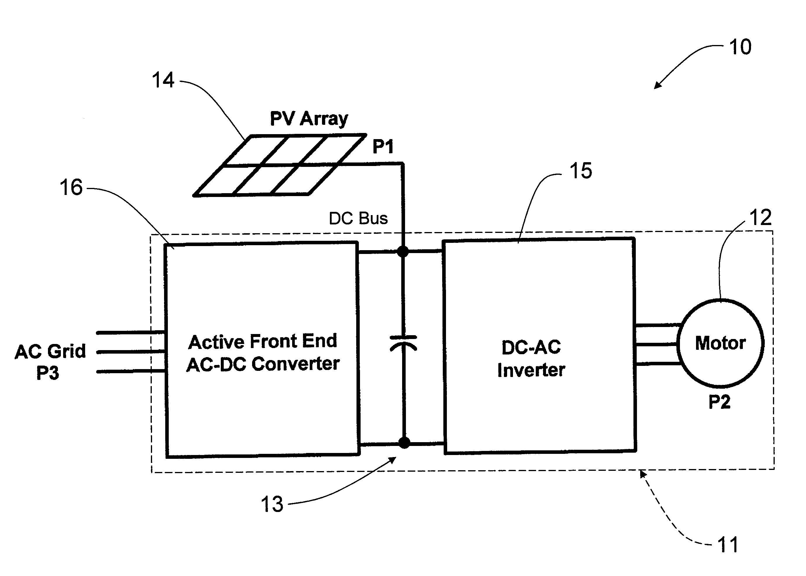
[0034]Referring to the drawings, an exemplary PV-integrated variable frequency drive system according to an embodiment of the invention is illustrated in FIG. 4 and shown generally at reference numeral 10. The system 10 uses a grid-tied variable frequency drive 11 (including motor 12) having a DC bus 13 directly modulated by a PV array 14, a DC-DC inverter 15, and a rectifier section or active front end 16 that acts as a grid-tied inverter during certain operating conditions, such as when the PV output is greater than the variable frequency drive load. This allows the variable frequency drive 11 to feed power back into the grid, if needed, for use in peak shaving, power quality, or backup applications. The drive 11 also includes an MPPT algorithm for detecting optimal operating points and continuously tracking the operation of the system 10.

[0035]In this approach, the PV array 14 is directly interfaced to the DC bus 13 which allows for modifications to the front-end 16 and back-end ...


PUM


Abstract

A photovoltaic (PV) integrated variable frequency drive system having a variable frequency drive and an energy source. The variable frequency drive having a back end inverter, a DC bus electrically connected to the back end inverter, and an active front end electrically connected to the DC bus to facilitate bi-directional power flow to and from a power grid. The energy source being electrically connected to the DC bus.

Description

BACKGROUND OF THE INVENTION[0001]The present invention relates generally to a multi-functional drive system, and more particularly to a photovoltaic (PV) integrated variable frequency drive system.[0002]As the drive to reduce CO2 emissions gathers momentum, alternative energy or distributed sources are gaining importance. These distributed sources include wind, tidal energy, and solar energy. In particular, solar energy, where light energy from the sun is converted into electrical energy using photovoltaic (PV) cells, is becoming one of the most prominent alternative energy resources. In addition to reducing harmful emissions, these distributed sources contribute several ancillary services to the power industry, such as peak power shaving, backup power, and spinning reserve support.[0003]PV-based systems are well known in the art. The most common structure of a grid-connected PV system is shown in FIG. 1. Most PV-based systems include a PV array, DC bus capacitors (not shown), an in...

Claims


Application Information

Patent Timeline
Patent Type & Authority Applications(United States)
IPC IPC(8): H02M5/458
CPCH02J1/102H02J1/108Y02E10/56H02M5/458H02M7/797H02M1/10
Inventor RAJAGOPALAN, SATISHMANSOOR, ARSHADLAI, JIH-SHENGKHAN, FAISAL
Owner ELECTRIC POWER RES INST INC
Why Eureka
Try Eureka