
Ultraviolet light emitting diode package

Active Publication Date: 2010-03-25
SEOUL VIOSYS CO LTD
View PDF5 Cites 34 Cited by
  • Summary
  • Abstract
  • Description
  • Claims
  • Application Information

AI Technical Summary

Benefits of technology

[0011]Accordingly, an object of the present invention is to provide a UV LED package, wherein using an LED chip for emitting UV light with a peak wavelength of 350 nm or less, a member for protecting the LED chip includes a non-yellowing material to thereby minimize the deterioration in performance and lifespan of the LED chip depending on time.
[0012]Another object of the present invention is to provide a UV LED package including a structure in which a large amount of heat caused when producing UV with a short wavelength is easily dissipated to the outside to thereby improve performance and lifespan of the UV LED package.
[0016]According to the embodiments of the present invention, it is possible to implement a UV LED package used to produce UV light with a short wavelength and having superior performance in terms of antibiosis, anti-dust, purification, sterilization and the like. Although high energy (particularly, heat energy) is generated when producing the UV light with a short wavelength, a yellowing phenomenon is hardly caused in a protective member around an LED chip. Accordingly, the degradation of the performance and lifespan of the LED chip depending on time can be minimized.

Problems solved by technology

However, the increase of the input power causes junction temperature of the LED to increase.
The increase of the junction temperature of the LED results in decrease of photometric efficiency indicating a degree where input energy is converted into visible light.
However, a light emitting diode package (hereinafter, referred to as an LED package) having such a structure, i.e., an LED package capable of obtaining high luminous power with large input power, has not been suggested in various structures and shapes.
This is because the LED package has a technical difficulty in commercialization in spite of its simple structure.
In particular, since it is not easy to analyze the heat generated from the LED package itself and there are few specialists therefor, the development of the LED package is restrictedly performed.
Nevertheless, as UV light has a shorter wavelength, the performance and lifespan of an LED package including a UV LED are more degraded.
For this reason, there is a limit to development of a UV LED with a short peak wavelength.

Method used


Image

  • Ultraviolet light emitting diode package
  • Ultraviolet light emitting diode package
  • Ultraviolet light emitting diode package

Examples


Embodiment Construction

[0030]Other objects and advantages of the present invention will be apparently understood from descriptions of the following embodiments.

[0031]Hereinafter, although the embodiments of the present invention will be described in detail with reference to the accompanying drawings, the embodiments are provided only for illustrative purposes and the present invention is not limited to the embodiments.

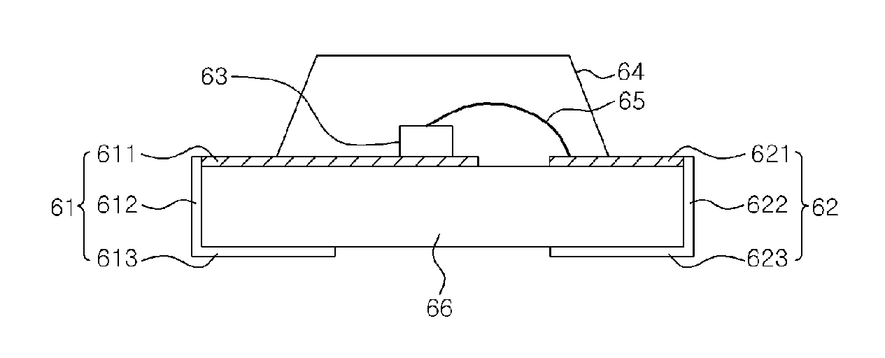
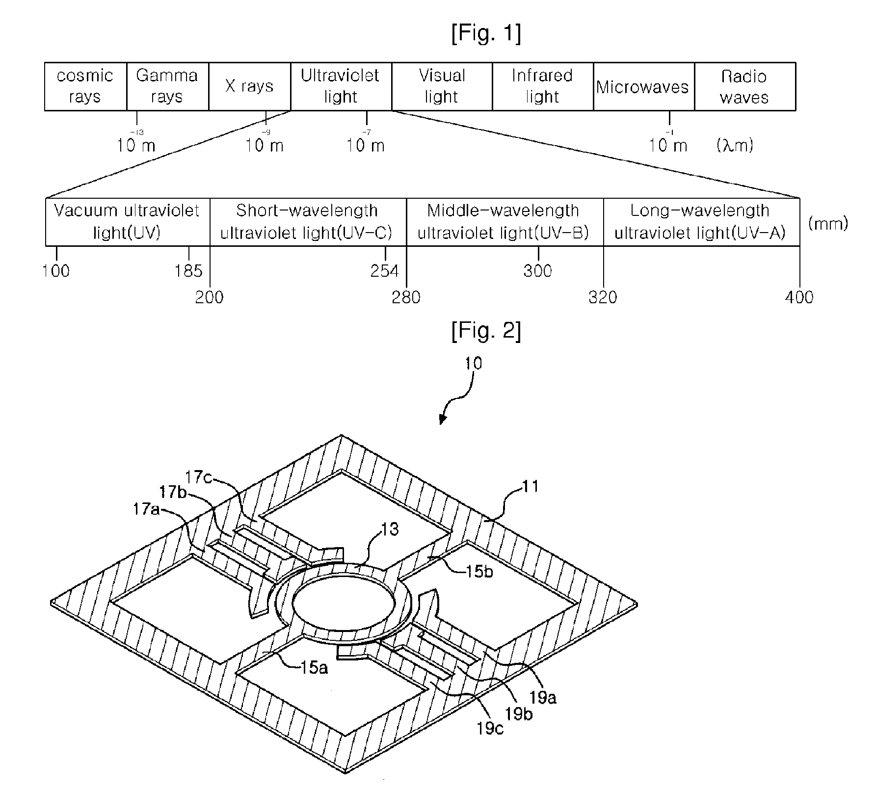
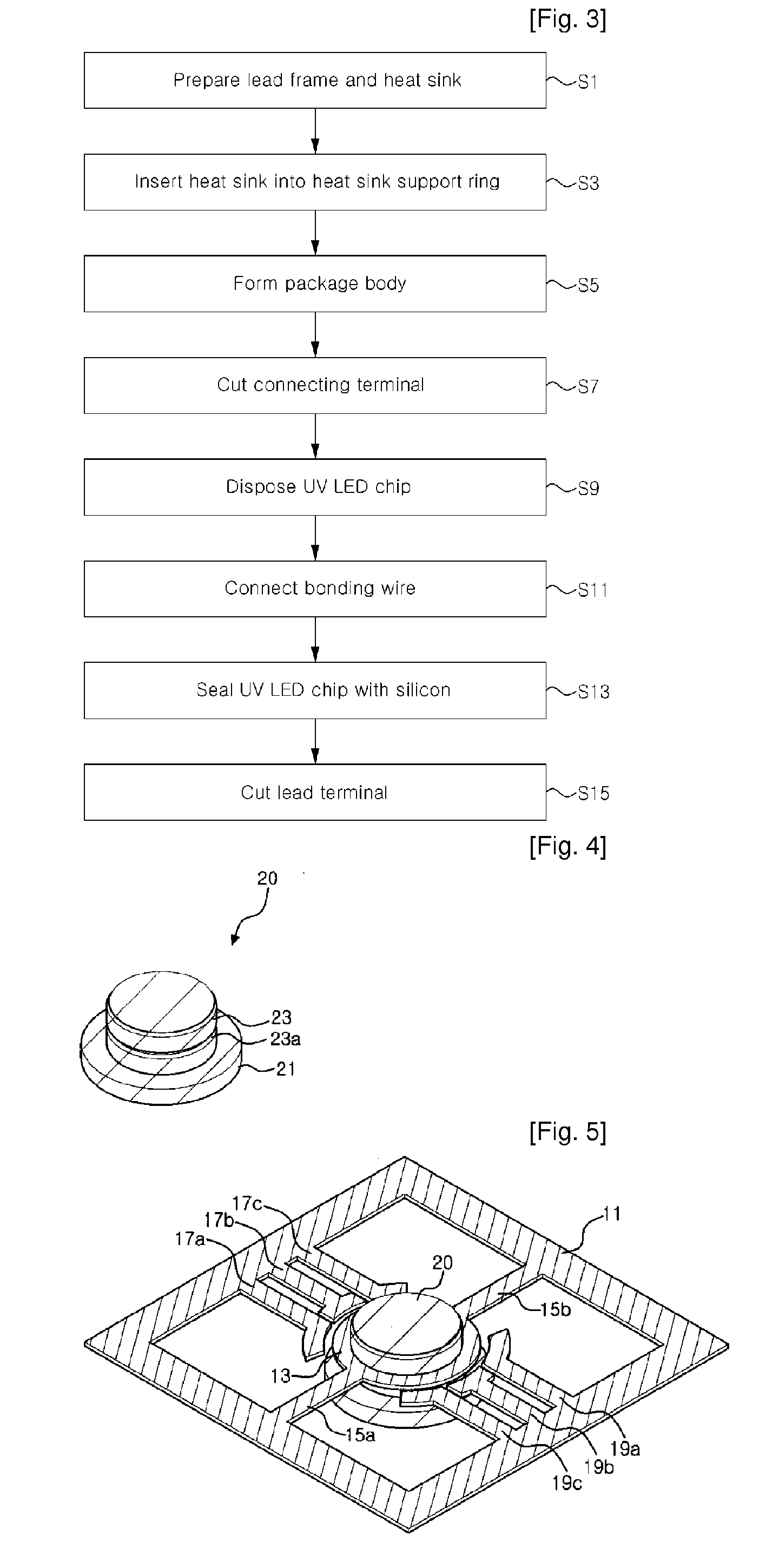
[0032]Referring to FIG. 1, light emitted with a peak wavelength of 350 nm or less is in a short wavelength UV range. The UV light is divided into UVA (400 to 320 nm) that has a relatively long wavelength, UVB (320 to 280 nm) that has a middle wavelength, and UVC (280 nm or less) that has a short wavelength and is referred to as a sterilization wavelength, depending on an influence on human bodies and environments. Long wavelength UV with a wavelength of over 350 nm is generally used in a package using a UV LED chip, which is because reliability may be degraded due to heat produced when UV wi...


PUM


Abstract

An ultraviolet light emitting diode package for emitting ultraviolet light is disclosed. The ultraviolet light emitting diode package comprises an LED chip emitting light with a peak wavelength of 350 nm or less, and a protective member provided so that surroundings of the LED chip is covered to protect the LED chip, the protective member having a non-yellowing property to energy from the LED chip.

Description

CROSS REFERENCE TO RELATED APPLICATIONS[0001]This application is the National Stage of International Application No. PCT / KR2007 / 004480, filed Sep. 18, 2007, and claims priority from and the benefit of Korean Patent Application No. 10-2006-0094917, filed on Sep. 28, 2006, Korean Patent Application No. 10-2006-0095847, filed on Sep. 29, 2006, and Korean Patent Application No. 10-2006-0095849, filed on Sep. 29, 2006, which are all hereby incorporated by reference for all purposes as if fully set forth herein.BACKGROUND OF THE INVENTION[0002]1. Field of the Invention[0003]The present invention relates to an ultraviolet light emitting diode package, and more particularly, to an ultraviolet light emitting diode package including a light emitting diode chip for emitting light with a peak wavelength of 350 nm or less.[0004]2. Discussion of the Background[0005]Recently, a light emitting diode (LED) has been used for various applications including light sources for illumination, sterilization...

Claims


Application Information

Patent Timeline
IPC IPC(8): H01L33/00H01L33/56H01L33/64
CPCH01L33/60H01L33/642H01L25/0753H01L33/56H01L2224/48091H01L2924/00014H01L2924/00
Inventor BAE, JEONG SUKKIM, JAE JOKIM, DO HYUNGKAL, DAE SUNG
Owner SEOUL VIOSYS CO LTD
Learn More