Drawer type cooking device

a cooking device and a drawing board technology, applied in the direction of dynamo-electric converter control, muffle furnace, furnace, etc., to achieve the effect of convenient user operation, easy removal, and smooth change of position

Active Publication Date: 2010-03-25
SHARP KK
View PDF1 Cites 5 Cited by
  • Summary
  • Abstract
  • Description
  • Claims
  • Application Information

AI Technical Summary

Benefits of technology

[0024]With the drawer type cooking device, the drawer body can be drawn out of or pushed into the heating chamber by the slide mechanism that slidingly guides the drawer body in the draw-out direction outside the heating chamber, and the open / close door closes the heating chamber with the drawer body being pushed into the heating chamber to prevent leakage of microwaves to the outside during cooking. The heating container of the drawer body is separably connected to the inner side wall of the open / close door, and thus with the drawer body being drawn out, a connecting portion connecting the heating container to the inner side wall of the open / close door becomes accessible from above, and the connecting portion is separated to allow the heating container to be disconnected from the open / close door. The heating container separated from the open / close door can be taken out through a space opened above the open / close door and the heating chamber.
[0032]The heating container has a simple outer shape similar to a rectangular shape, and simply interposing a sheet of a foam or the like as a shock absorber can prevent contact or collision in the production process. The drawer body has a simple rectangular box shape with an open maximum surface. Thus, even if coating is performed after assembling, there is no recess in which a treatment liquid remains, and the treatment liquid can be substantially completely removed simply by draining with a typical method such as leaving the drawer body with the open surface directed downward, providing a slight vibration, or blowing with dry air.

Problems solved by technology

Thus, even if a user has insufficient physical ability such as insufficient muscle force, eyesight or hearing, the user can close the door without a need to push the door against a repulsive force of a latch.

Method used


Image

  • Drawer type cooking device
  • Drawer type cooking device
  • Drawer type cooking device

Examples


Embodiment Construction

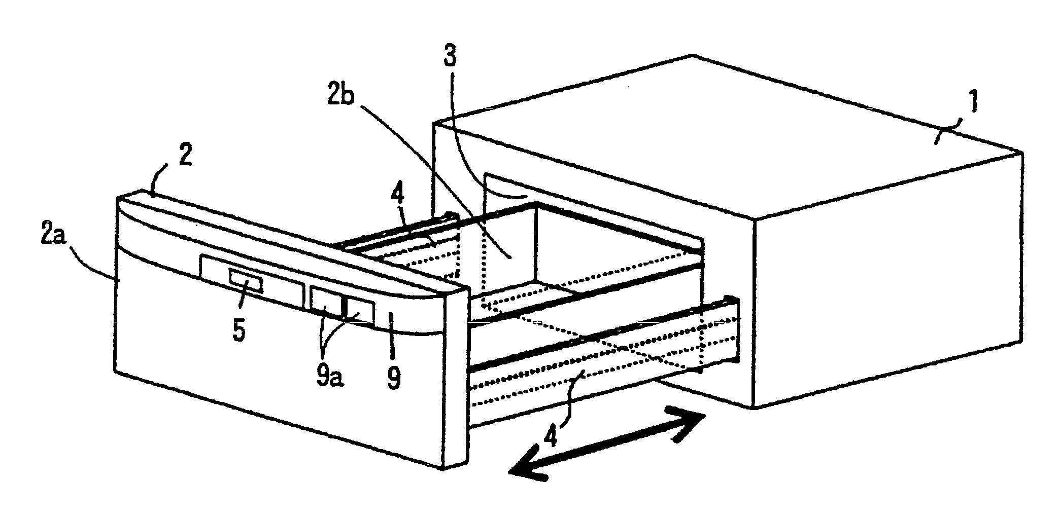
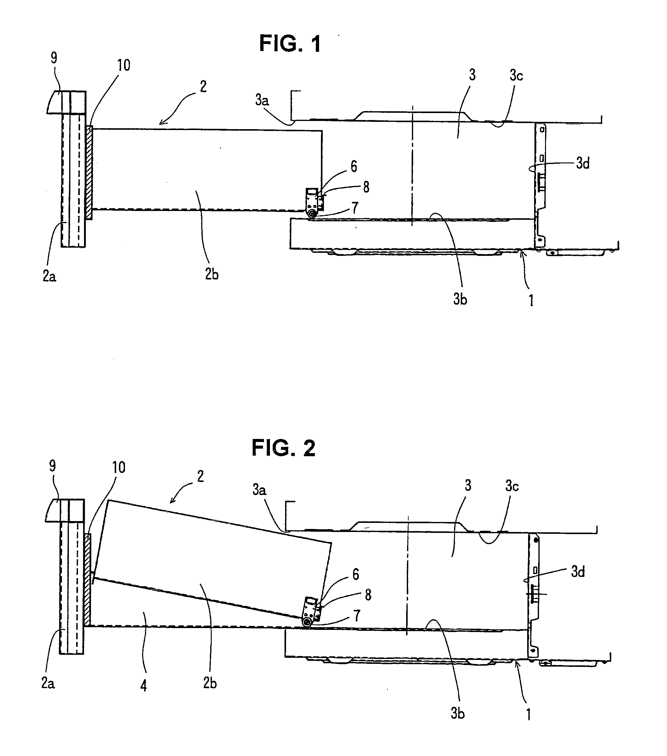
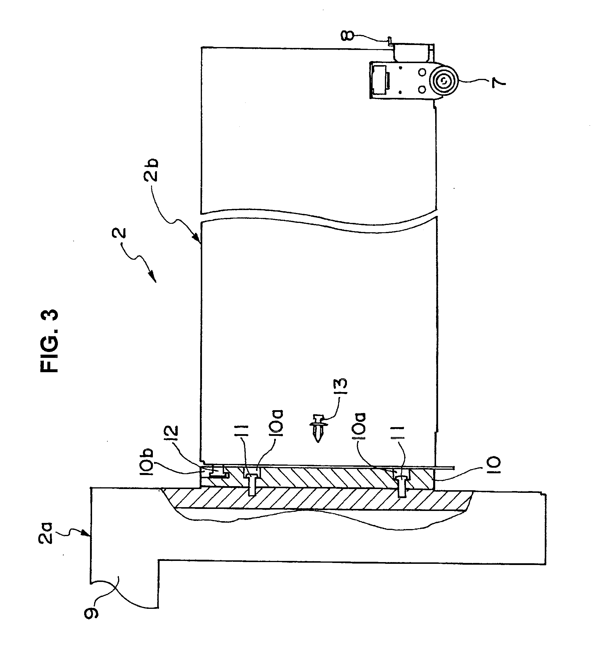
[0038]Now, an embodiment of a drawer type cooking device according to the present invention will be described with reference to the accompanying drawings. FIG. 1 is a side sectional view of the embodiment of the drawer type cooking device according to the present invention, FIG. 2 shows a heating container separated from an open / close door being taken out in the drawer type cooking device in FIG. 1, and FIG. 3 is a sectional view of an example of a separable locking structure between the open / close door and the heating container. The configuration of the cooking device may be the same as that in FIGS. 4 and 5 except a structure of a drawer body.

[0039]In the drawer type cooking device in FIG. 1, the drawer body 2 is slidingly guided in a draw-out direction by a slide mechanism 4 outside a heating chamber 3 formed in the cooking device body 1, and can be drawn out of or pushed into the heating chamber 3. A drive force from a drive mechanism such as a DC motor is transmitted to the sli...


PUM


Abstract

In a built-in drawer type cooking device, an open / close door 2a and a heating container 2b that constitute a drawer body 2 are separably connected to each other. The open / close door 2a and the heating container 2b are connected via an insulator 10 to prevent a discharge phenomenon due to emission of microwaves. The open / close door 2a and the heating container 2b can be separated from each other with the drawer body 2 being drawn out, and thus the heating container 2b can be taken out of the cooking device and cleaned or wholly washed. Also, an inner wall surface of a heating chamber 3 that is easily contaminated can be cleaned while being visually checked. The heating container 2b and the open / close door 2a are separately produced, and then can be individually stored, conveyed and stacked, thereby reducing a rejection rate due to deformation and increasing productivity in an assembling process.

Description

[0001]The present application is based on and claims priority of Japanese patent application No. 2008-240923 filed on Sep. 19, 2008, the entire contents of which are hereby incorporated by reference.BACKGROUND OF THE INVENTION[0002]1. Field of the Invention[0003]The present invention relates to a drawer type cooking device in which a heating container that contains an object to be heated can be drawn out of a heating chamber formed in a body of the cooking device by an operation of an open / close door.[0004]2. Description of the Related Art[0005]Conventionally, a cooking device has been proposed including: a device body including a cooking chamber that contains an object to be cooked; an open / close door that blocks off the cooking chamber from outside; a bottom plate that interlocks with the open / close door; a slide mechanism that slides the bottom plate; a motor that drives the bottom plate; transmission means that transmits a drive force of the motor to the bottom plate; a latch de...

Claims


Application Information

Patent Timeline
Patent Type & Authority Applications(United States)
IPC IPC(8): A21B1/00
CPCF24C15/02
Inventor UNO, MASAYUKI
Owner SHARP KK
Why Eureka
Try Eureka