Film deposition apparatus, film deposition method, and computer readable storage medium

Inactive Publication Date: 2010-03-18
TOKYO ELECTRON LTD
View PDF3 Cites 27 Cited by
  • Summary
  • Abstract
  • Description
  • Claims
  • Application Information

AI Technical Summary

Benefits of technology

[0010]In a batch-type chemical vapor deposition (CVD) apparatus, a process tube tends to be larger because several ten through one hundred wafers are housed in the process tube. Therefore, it takes a long time to purge the process tube when a first source gas is switched to a second source gas and vice versa. In addition, because the number of cycles may reach several hundred, it takes a longer time

Problems solved by technology

Therefore, it takes a long time to purge the process tube when a first source gas is switched to a second source gas and vice versa.
In addition, because the number of cycles may reach several hundred, it takes a longer time to carry out one run of film deposition, which may cause a problem of an increased turn

Method used


Image

  • Film deposition apparatus, film deposition method, and computer readable storage medium
  • Film deposition apparatus, film deposition method, and computer readable storage medium
  • Film deposition apparatus, film deposition method, and computer readable storage medium

Examples


Embodiment Construction

[0022]According to an embodiment of the present invention, there is provided a film deposition apparatus that can reduce a process time, a film deposition method using the film deposition apparatus, and a computer readable storage medium that stores a computer program for causing the film deposition apparatus to carry out the film deposition method.

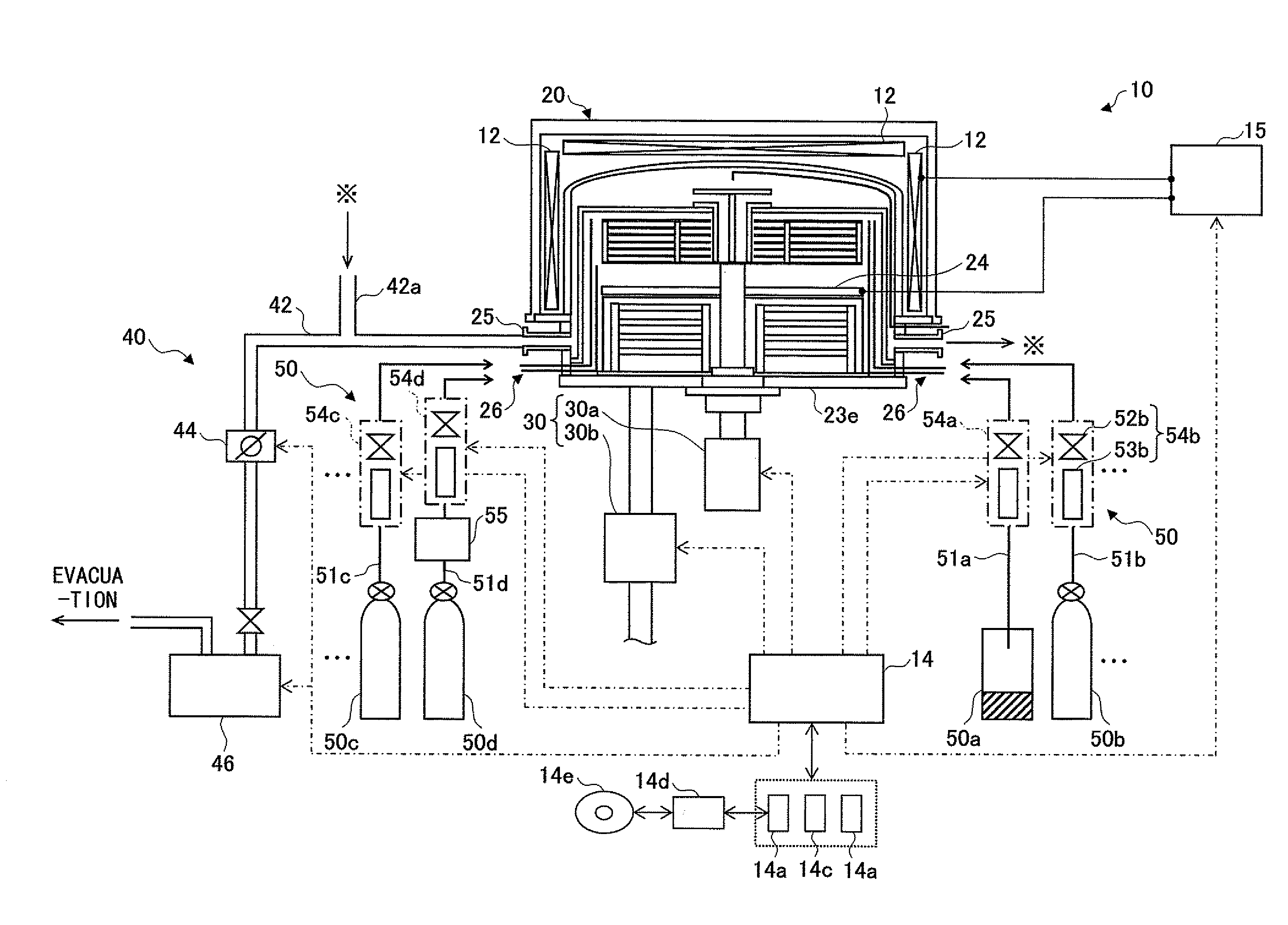
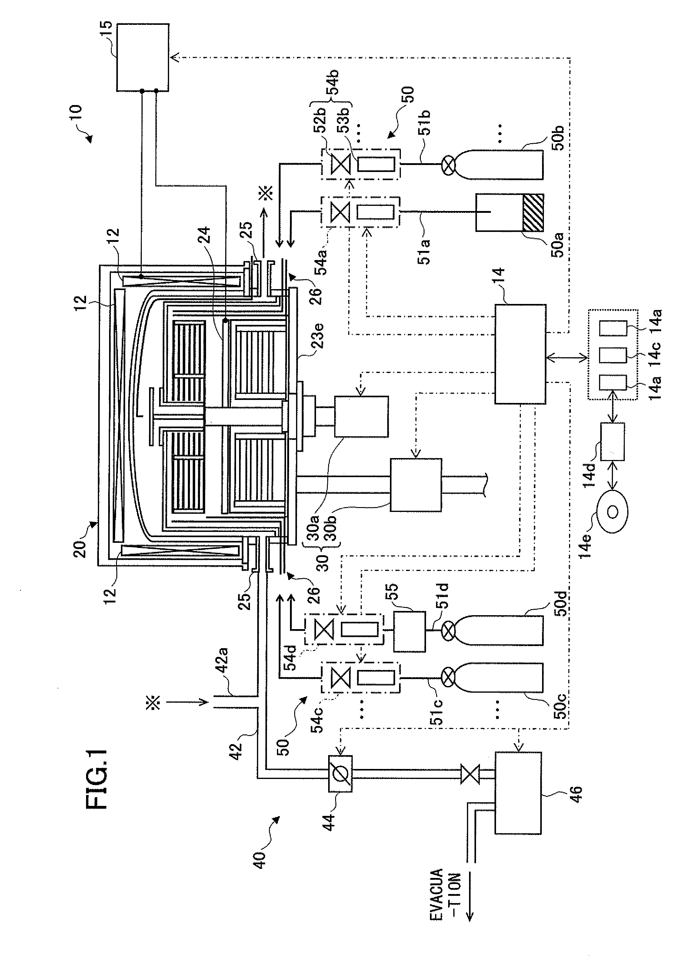
[0023]Non-limiting, exemplary embodiments of the present invention will now be described with reference to the accompanying drawings. In the drawings, the same or corresponding reference numbers and symbols are given to the same or corresponding members or components. It is noted that the drawings are illustrative of the invention, and there is no intention to indicate scale or relative proportions among the members or components. Therefore, the specific size should be determined by a person having ordinary skill in the art in view of the following non-limiting embodiments. In addition, while a film deposition apparatus and method accordi...


PUM


Abstract

A film deposition apparatus includes a reaction chamber evacuatable to a reduced pressure; a substrate holding portion rotatably provided in the reaction chamber and configured to hold a substrate; a first reaction gas supplying portion configured to flow a first reaction gas from an outer edge portion toward a center portion of the substrate holding portion; a second reaction gas supplying portion configured to flow a second reaction gas from an outer edge portion toward a center portion of the substrate holding portion; a separation gas supplying portion configured to flow a separation gas from an outer edge portion toward a center portion of the substrate holding portion, the separation gas supplying portion being arranged between the first and the second gas supplying portions; and an evacuation portion located in the center portion of the substrate holding portion in order to evacuate the first, the second, and the separation gases.

Description

CROSS-REFERENCE TO RELATED APPLICATIONS[0001]The present application is based on Japanese Patent Application No. 2008-238439 filed with the Japanese Patent Office on Sep. 17, 2008, the entire contents of which are hereby incorporated herein by reference.BACKGROUND OF THE INVENTION[0002]1. Field of the Invention[0003]The present invention relates to a film deposition apparatus and a film deposition method for depositing a film on a substrate by carrying out plural cycles of supplying in turn at least two source gases to the substrate in order to form plural layers of a reaction product, and a computer readable storage medium storing a computer program for carrying out the film deposition method.[0004]2. Description of the Related Art[0005]Along with further miniaturization of a circuit pattern in semiconductor devices, various films constituting the semiconductor devices are required to be thinner and more uniform. As a film deposition method that can address such requirements, a so-...

Claims


Application Information

Patent Timeline
IPC IPC(8): H01L21/302C23C16/00B05C11/10
CPCC23C16/345C23C16/40C23C16/401H01L21/68771C23C16/45551H01L21/67757H01L21/68764C23C16/45546H01L21/02H01L21/205
Inventor KATO, HITOSHIOBARA, KAZUTERU
Owner TOKYO ELECTRON LTD
Why Eureka
Try Eureka