
Recording mark formation method, information recording device, information recording method, and information recording medium

a recording mark and formation method technology, applied in the field of recording mark formation methods, information recording devices, information recording methods, information recording mediums, can solve the problems of difficulty in forming a recording mark with a uniform width as a whole, and shortage of an increase in the temperature of the medium, so as to reduce the number of parameters, uniform width of the recording mark in the resting period, and uniform width

Inactive Publication Date: 2010-03-18
SHARP KK +1
View PDF3 Cites 0 Cited by
  • Summary
  • Abstract
  • Description
  • Claims
  • Application Information

AI Technical Summary

Benefits of technology

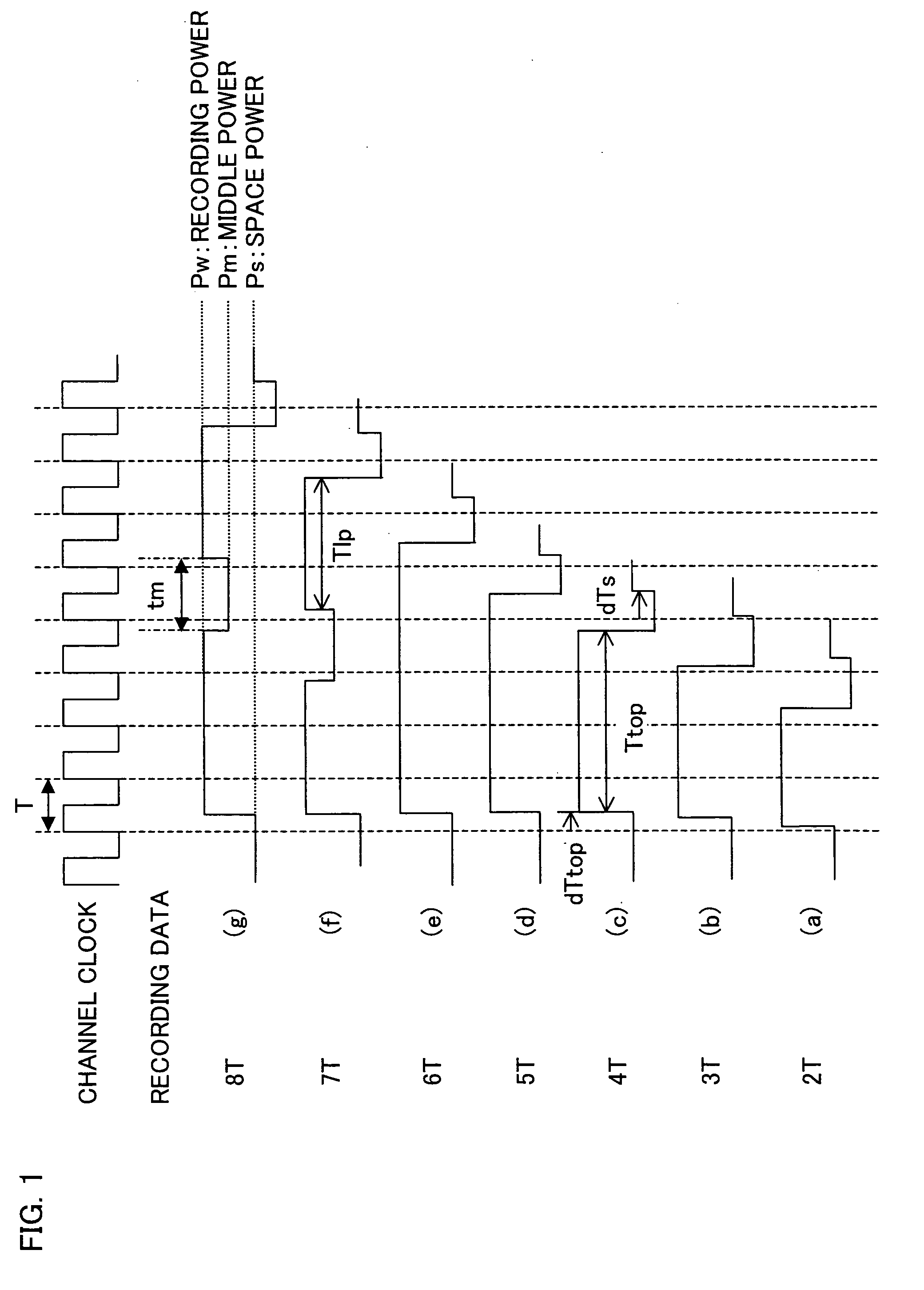
[0009]Further, in a recording method in which the controlling and recording method is applied to a recording waveform of Patent Document 1, a recording power is set to be low. Consequently, as recording velocity increases, energy density per unit time that is poured into the medium drops. As the mark length of the recording mark is longer, irradiation period during which laser of a middle power (recording power lower than the above recording power) is irradiated (resting period) gets longer, resulting in smaller energy poured into the medium. This causes the recording mark width at the resting period to be narrower, which makes it difficult to form a recording mark with a uniform width as a whole. That is, as the recording mark gets longer, the resting period gets longer, resulting in shortage of an increase in the temperature of the medium.
[0023]This allows formation of a recording mark with a uniform width by use of a low laser power and allows reduction of the number of parameters for determining a recording waveform, when forming a long recording mark.

Problems solved by technology

However, the aforementioned recording method has the following problems.
As a result, it is difficult to form a recording mark with a uniform width (a width in a direction perpendicular to a track direction).
This causes the recording mark width at the resting period to be narrower, which makes it difficult to form a recording mark with a uniform width as a whole.
That is, as the recording mark gets longer, the resting period gets longer, resulting in shortage of an increase in the temperature of the medium.

Method used


Image

  • Recording mark formation method, information recording device, information recording method, and information recording medium
  • Recording mark formation method, information recording device, information recording method, and information recording medium
  • Recording mark formation method, information recording device, information recording method, and information recording medium

Examples


Embodiment Construction

[0046]The following explains an embodiment of the present invention with reference to drawings.

[0047]An information recording / reproducing device (present device; information recording device) of the present embodiment records information (data; digital data) in an optical disc (information recording medium) such as a CD and a DVD, and reproduces the information from the optical disc.

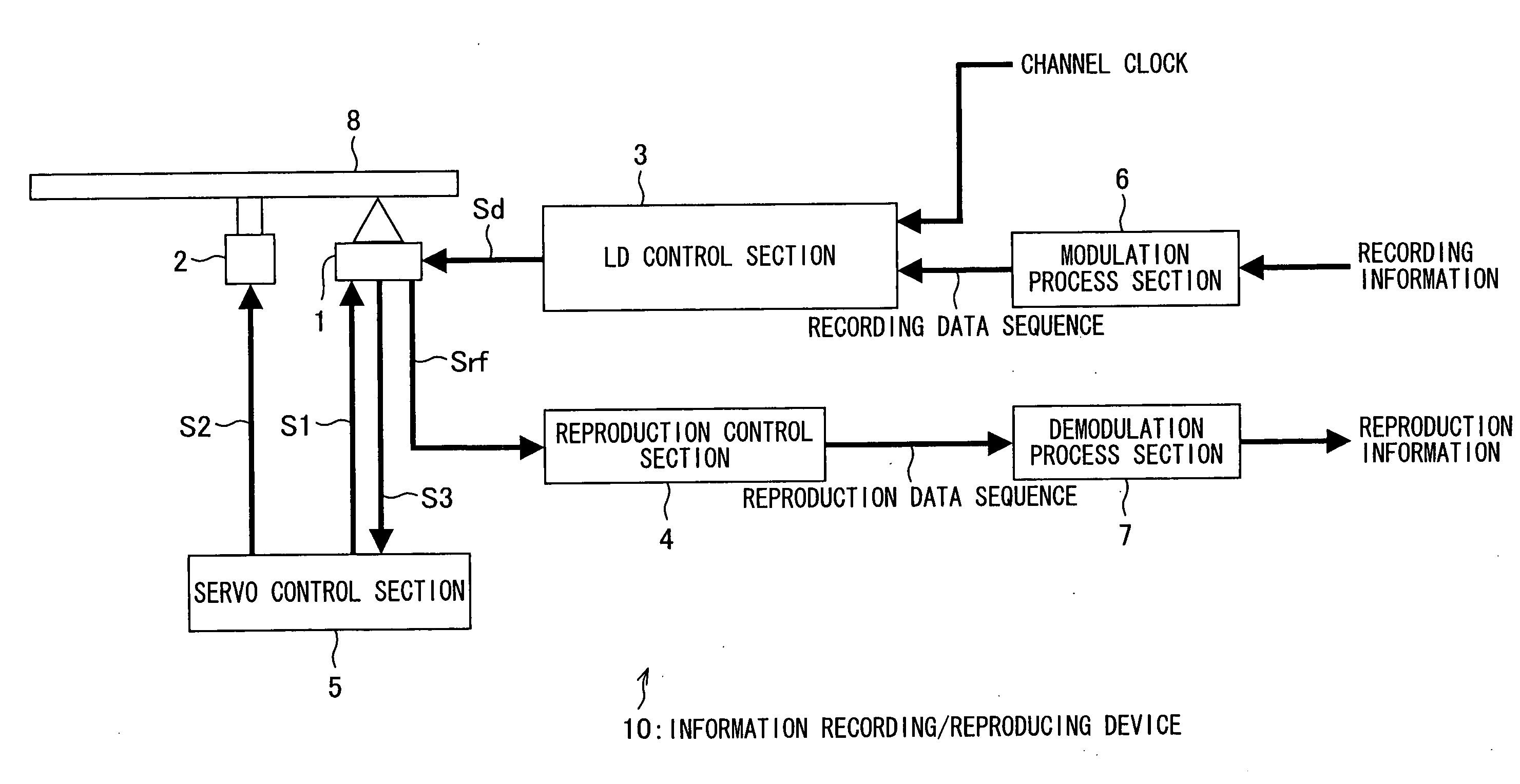
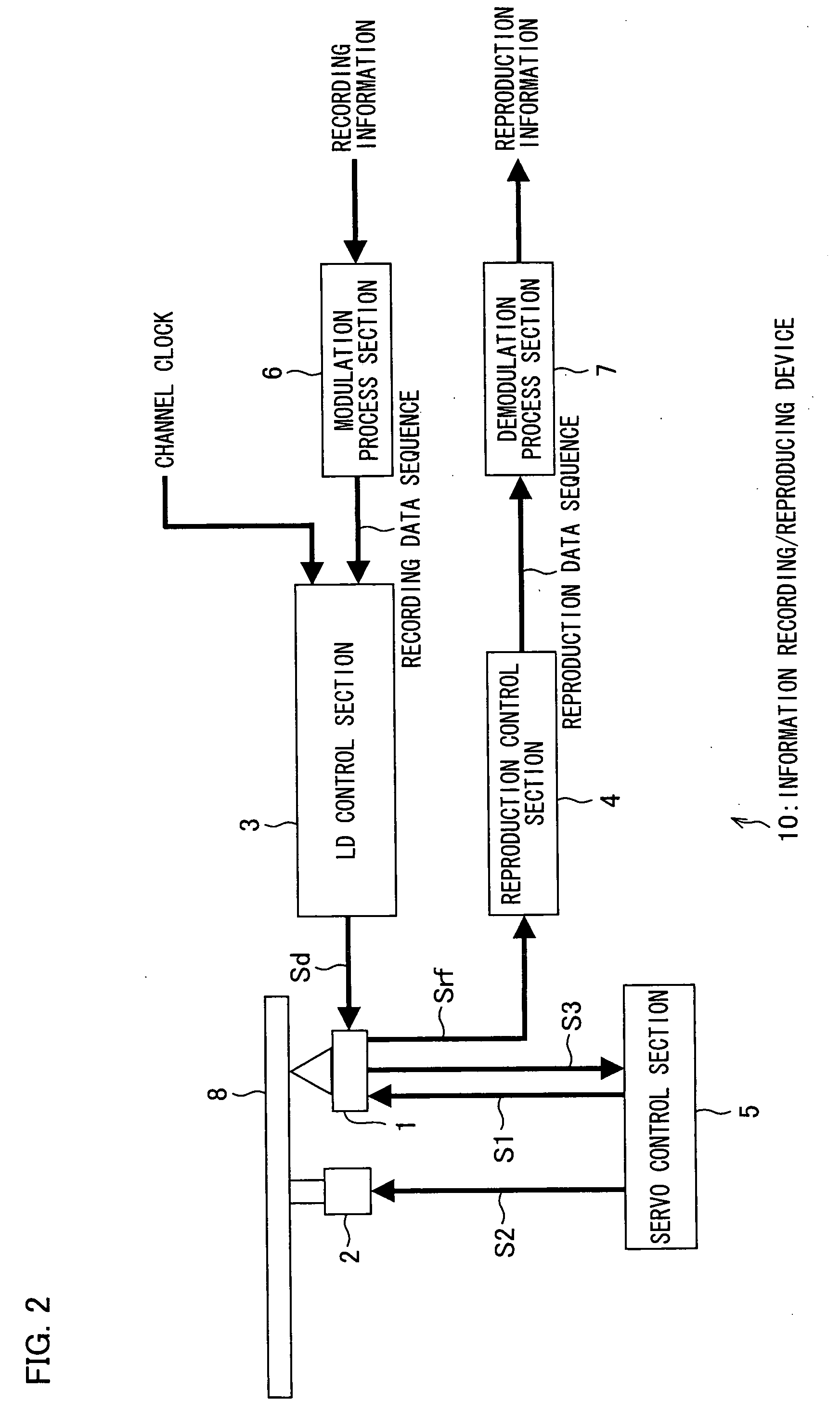
[0048]As illustrated in FIG. 2, a present device 10 includes an optical pickup 1, a spindle motor 2, an LD control section 3, a reproduction control section 4, a servo control section 5, a modulation process section 6, and a demodulation process section 7. An optical disc 8 is positioned to face the present device 10. The LD control section 3, the modulation process section 6, the servo control section 5, and the optical pickup 1 constitute recording mark formation means.

[Structure of Optical Disc]

[0049]The optical disc 8 can be used in a next-generation DVD device that has high channel clock frequency a...


PUM

PropertyMeasurementUnit
frequencyaaaaaaaaaa
linear velocityaaaaaaaaaa
thicknessaaaaaaaaaa

Abstract

In an information recording / reproducing device, a resting period (tm) is set to be constant regardless of a mark length of a recording mark and regardless of the number of divided recording pulses. Consequently, it is possible to provide an information recording device, an information recording method, and an information recording medium, each allowing formation of a recording mark with a uniform width by use of a low laser power and allowing reduction of the number of parameters for determining a recording waveform, when forming a long recording mark.

Description

TECHNICAL FIELD[0001]The present invention relates to: a recording mark formation method, an information recording device, and an information recording method, each of which is used for a high-density optical disc; and an information recording medium that is a high-density optical disc.BACKGROUND ART[0002]Optical discs such as CDs and DVDs, for which red semiconductor laser is used, have been widely used as information recording media for recording digital data (information). Examples of the optical discs include: an optical disc in which data is unrecordable and unrewritable (ROM optical disc); an optical disc in which data is recordable but unrewritable (recordable optical disc); and an optical disc in which data is rewritable (rewritable optical disc).[0003]Information is recorded on an optical disc by irradiating laser light to a recording surface of the optical disc. A portion of the recording surface of the optical disc to which laser light is irradiated increases its temperat...

Claims


Application Information

Patent Timeline
Patent Type & Authority Applications(United States)
IPC IPC(8): G11B7/00
CPCG11B7/00456G11B7/00455
Inventor ETOH, ATSUSHI
Owner SHARP KK
Learn More