Lens unit

a technology of lens unit and lens body, which is applied in the field of lens unit, can solve the problems of increasing the number of members as a problem, affecting the image affecting the quality of the image, so as to reduce the number of parts, reduce the change of angle, and reduce the effect of curvature of interconnection

Inactive Publication Date: 2010-03-18
SHARP KK
View PDF8 Cites 2 Cited by
  • Summary
  • Abstract
  • Description
  • Claims
  • Application Information

AI Technical Summary

Benefits of technology

[0028]As is apparent from the above, in the lens unit according to the present invention, because the one end of the interconnection for supplying power to the driving section of the light amount control section is disposed and held between the lens holder and the shutter unit, the interconnection is prevented from being separated from the shutter unit, which eliminates the need for any member for securing the interconnection to the shutter unit so that the parts count can be reduced.
[0029]Furthermore, the one end of the interconnection is placed between the lens holder and the shutter unit. Therefore, unwanted light directed to the interconnection is blocked by the lens holder and the shutter unit, so that formation of ghosts in images due to reflection of unwanted light by the interconnection is prevented.
[0030]If the interconnection is routed so as not undergo restraints during a process from when being bent toward the subject side until when being secured to the side wall of the casing, the interconnection is prevented from undergoing undue stress during movement of the lens holder.
[0031]When the width of the band-shaped interconnection in the region in which the interconnection is curved is narrower than the width of the other regions of the interconnection, the force that the lens holder receives from the curved portion of the interconnection along with the movement of the lens holder is made smaller. As a consequence, it becomes possible to decrease changes of an angle of the interconnection with respect to the optical axis of the lens holder to lessen effects of curvature of the interconnection on the image quality.

Problems solved by technology

However, the conventional lens tube disclosed in Patent Literature 1 has the following problems.
Thus, members count increases as a problem.
Also, since the FPC 1 on the shutter unit side needs to be hooked to the hooking holder 4 provided in the annular lid member 3, the assembling work becomes more complex as another problem.
There is also a problem that since the FPC 1 undergoes an abrupt bending stress applied to the U-shaped portion 5 hooked to the hooking holder 4, disconnection may occur to conductive portions of the FPC 1.

Method used


Image

  • Lens unit
  • Lens unit
  • Lens unit

Examples


Embodiment Construction

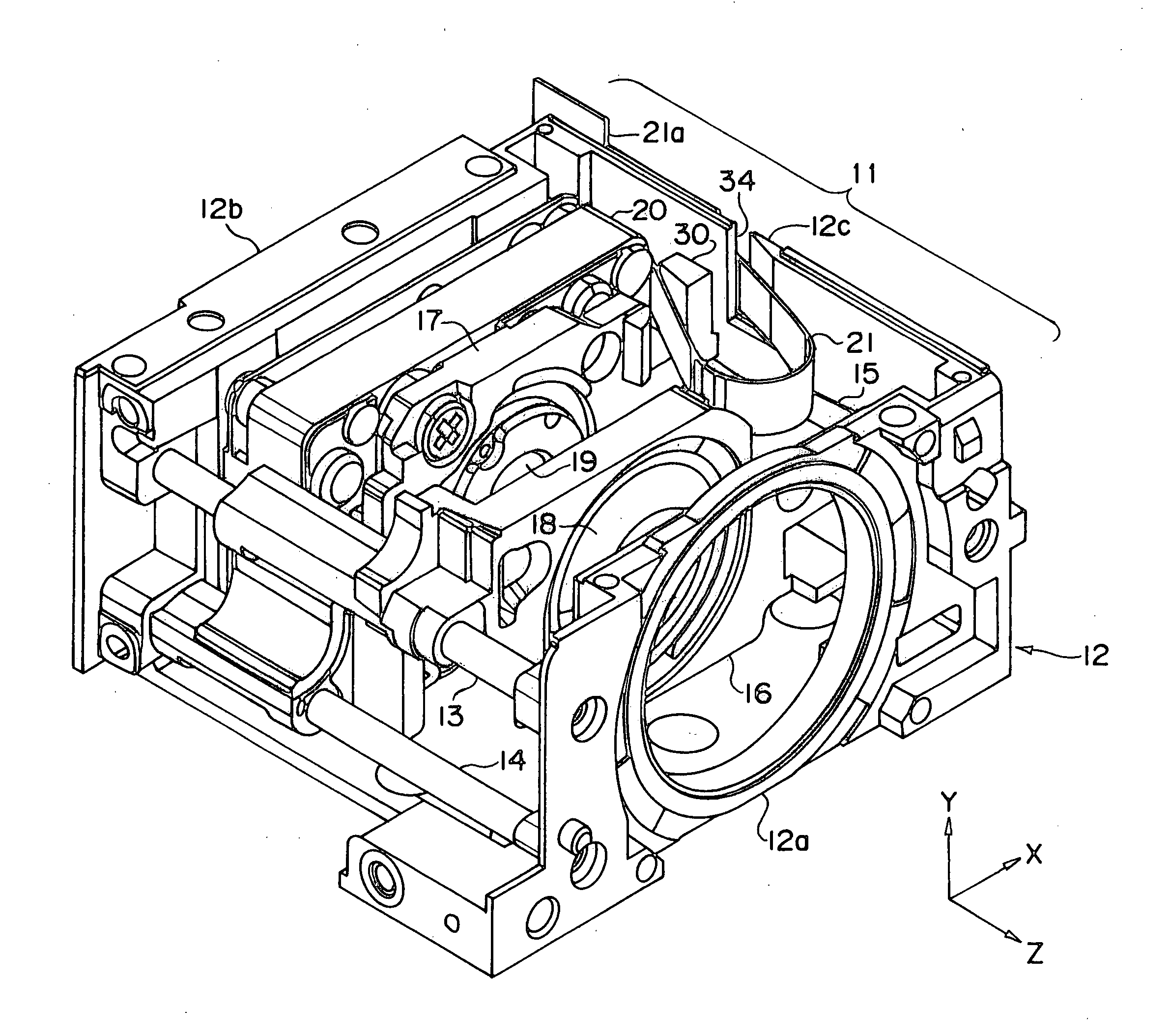
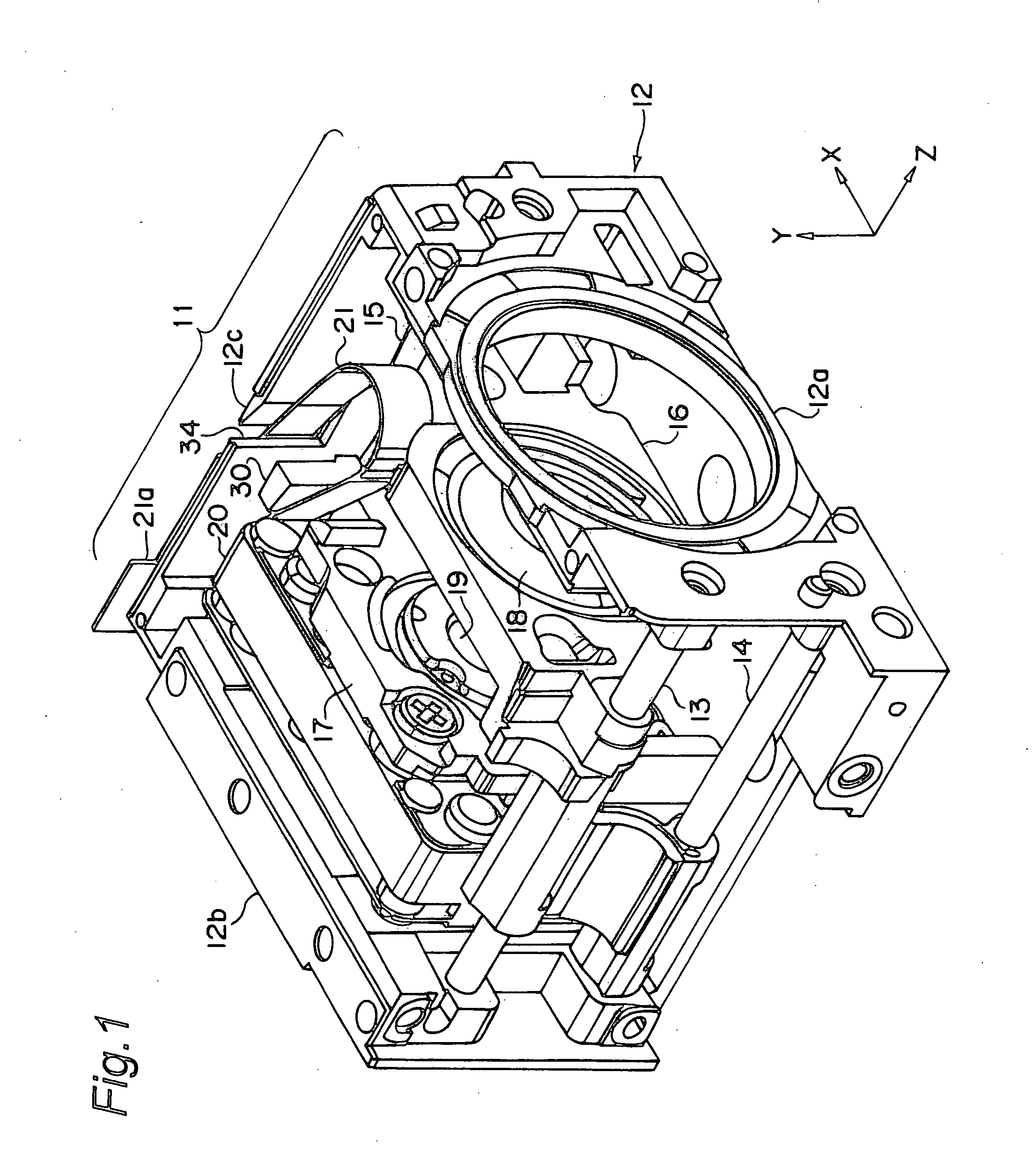
[0039]Hereinbelow, the present invention will be described in detail by way of embodiments thereof illustrated in the accompanying drawings. FIGS. 1 and 2 are perspective views showing a schematic construction of an optical unit in which a lens unit of this embodiment is incorporated. In FIGS. 1 and 2, the optical unit 11 is formed in a generally rectangular-parallelepiped shape. Hereinbelow, a Z axis is set along an optical-axis direction while X and Y axes are set along two sides, respectively, of the rectangular parallelepiped of the optical unit 11 orthogonal to the optical axis.

[0040]The optical unit 11 is so constructed that optical components are mounted on an optical base 12 composed of a subject-side wall 12a, an image pickup-side wall 12b and a side wall 12c which is a Y-Z plane. Therefore, light coming incident from the subject-side wall 12a is thrown onto image sensors (not shown) provided on the image pickup-side wall 12b side.

[0041]Also in the optical unit 11, cylindri...


PUM


Abstract

One end of an FPC (21) for supplying power to the driving section of a light amount control section provided in a shutter unit (20) is disposed between a second lens holder (17) and the shutter unit (20) secured to this second lens holder (17) and is held between the second lens holder (17) and the shutter unit (20). Thus, the FPC (21) is prevented from being spaced apart from the shutter unit (20), and a member for securing the FPC (21) to the shutter unit (20) is eliminated, reducing the number of part items. Further, the second lens holder (17) and the shutter unit (20) blocks unwanted light toward the FPC (21), so that a ghost image is prevented from appearing on an image due to unwanted light reflected on the FPC (21).

Description

TECHNICAL FIELD[0001]The present invention relates to a lens unit to be mounted on optical instruments such as cameras.BACKGROUND ART[0002]Conventionally, cameras and others including an image pickup optical system composed of plural lenses are in widespread use. In such a camera or the like, an image of a subject based on a light pencil incident on the image pickup optical system is formed on image sensors such as CCDs (Charge Coupled Devices) placed at specified positions. For such cameras, there is a desire for their further downsizing with a view to facilitating their incorporation into portable terminal equipment in addition to enhancements in zoom function, autofocus function or other higher functions and higher resolutions.[0003]Furthermore, cameras having the zoom function are, in general, so designed that a zoom lens group and a shutter unit are integrally moved so as to provide a smaller aperture. That is, the shutter unit is secured on a subject side of the integrally dri...

Claims


Application Information

Patent Timeline
Patent Type & Authority Applications(United States)
IPC IPC(8): G02B9/00
CPCG03B9/08G02B7/102
Inventor NISHIKAWA, MASAYUKIFUJITA, HIDEAKIINUI, TOSHIHARU
Owner SHARP KK
Why Eureka
Try Eureka