Compact pyroelectric sealed electron beam

a pyroelectric seal and electron beam technology, applied in the direction of discharge tube main electrodes, instruments, incadescent cooling arrangements, etc., can solve the problems of large dc power supplies (including transformers), inability to adapt to the ionization source flexibility, and inability to meet the requirements of high-voltage feedthroughs, etc., to achieve the effect of prolonging the life of the tub

Active Publication Date: 2010-03-18
EXCELLIMS CORP
View PDF9 Cites 15 Cited by
  • Summary
  • Abstract
  • Description
  • Claims
  • Application Information

AI Technical Summary

Problems solved by technology

However, these sources have drawbacks and lack the flexibility of an ionization source which launches energetic particles into the gas.
In addition, the high voltage at the cathode requires high-voltage feedthroughs that are large.
However, conventional technologies present issues with the size of DC power supplies (including the transformer), the size of the high voltage insulators and other issues dealing with high voltage such as arcing.
The electron current in these concepts is difficult to control and the devices are complex and large.
Bayssie, J. D. Brownridge, N. Kukhtarev, T. Kukhtarev, J. C. Wang, Nuclear Instruments and Methods in Physics Research B 241 (2005) 913-916, and Electron and positive ion acceleration with pyroelectric crystals, Jeffrey A. Geuther and Yaron Danon, Journal Of Applied Physics 97, 074109 (2005) However, it is difficult to control the voltage or the current of the device.
The present state of the art of pyroelectric electron beams lacks adequate current control, lacks continuous production, and has relatively low currents, making them unsuitable for applications for an Ion Mobility Spectrometer.
In addition, means of achieving a sealed tube with long lifetime and with sufficient stability has not been proposed to date.

Method used


Image

  • Compact pyroelectric sealed electron beam
  • Compact pyroelectric sealed electron beam
  • Compact pyroelectric sealed electron beam

Examples


Embodiment Construction

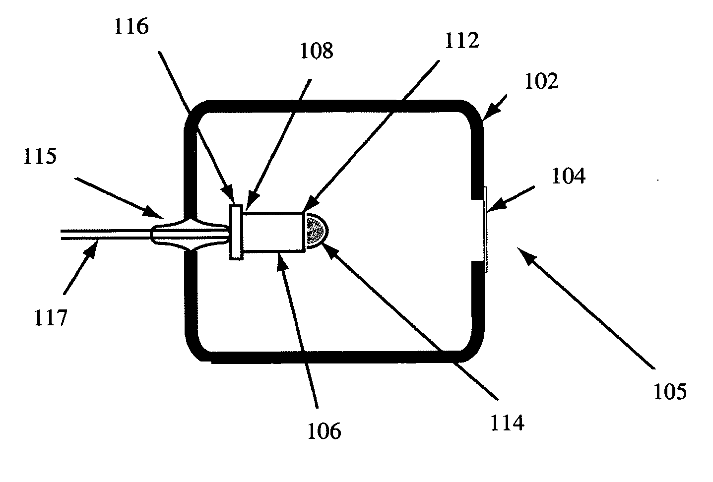
[0021]This electron beam generator invention using a pyroelectric crystal(s) can be used as a non-radioactive ionization source in any analytical instrument whereby a non-radioactive ionization source is necessary. For example, the electron beam ionization source and method is intended to be used in a similar fashion to a radioactive source such as Ni63.

[0022]The phrase “and / or,” as used herein in the specification and in the claims, should be understood to mean “either or both” of the elements so conjoined, i.e., elements that are conjunctively present in some cases and disjunctively present in other cases.

[0023]Unless otherwise specified in this document the term “ion mobility based detector” is intended to mean any device that separates ions based on their ion mobilities and / or mobility differences under the same or different physical and / or chemical conditions, the spectrometer may also include detecting the ions after the separation process. Many embodiments herein use the time...


PUM


Abstract

A non-radioactive source for Atmospheric Pressure Ionization is described. The electron-beam sealed tube uses a pyroelectric crystal(s). One end of the crystal is grounded while the other end has a metallic cap with sharp feature to generate an electron beam of a given energy. The rate of heating and / or cooling of the crystal is used to control the current generated from a tube. A heating and / or cooling element such as a Peltier element is useful for controlling the rate of cooling of the crystal. A thin window that is transparent to electrons but impervious to gases is needed in order to prolong the life of the tube and allow the extraction of the electrons. If needed, multiple crystals with independent heaters can be used to provide continuous operation of the device. The energy of the electrons can be determined through the appropriate choice of the radius of curvature of the sharp feature and the gap between the sharp feature and the window, while the opposite side of the crystal is at low voltage. The size of the gap and the radius of curvature of the sharp feature are determined by the filling gas nature and pressure.

Description

CROSS-REFERENCE TO RELATED APPLICATIONS[0001]The present application claims the benefit of and priority to corresponding U.S. Provisional Patent Application No. 60 / 980,115, filed Oct. 15, 2007 respectively, the entire content of the application is herein incorporated by reference.BACKGROUND OF THE INVENTION[0002]Atmospheric Pressure Ionization is used in analytical instruments, such as Atmospheric Pressure Chemical Ionization (APCI) Mass Spectrometry, and in detection devices. The detection devices can be either conventional Ion Mobility Spectrometers (IMS) or Differential Mobility Spectrometers (FAIMS). These devices typically use a small radioactive source that generates energetic particles (electrons, alpha particles) that when introduced into the surrounding gas ionize some atoms or molecules.[0003]There have been attempts to replace the radioactive source commonly used in APCI. There are corona discharges, uv-ionization, laser induced ionization, and other plasma discharges. Ho...

Claims


Application Information

Patent Timeline
Patent Type & Authority Applications(United States)
IPC IPC(8): H01J27/02
CPCH01J49/147
Inventor BROMBERG, LESLIEWU, CHING
Owner EXCELLIMS CORP
Why Eureka
Try Eureka