Method to correct imaging errors of an x-ray image intensifier system and associated x-ray image intensifier system

an x-ray image intensifier and imaging error technology, applied in the field of associated x-ray image intensifier system, can solve the problems of not being detected in this way, specific spatial positions would be measured, dynamic variations of local magnetic field strength, etc., to achieve cost reduction, high material cost, and simple operation

Inactive Publication Date: 2010-03-11
SIEMENS AG
View PDF5 Cites 1 Cited by
  • Summary
  • Abstract
  • Description
  • Claims
  • Application Information

AI Technical Summary

Benefits of technology

[0010]An object of the present invention is to provide a method for correction of imaging errors (in particular of distortions due to magnetic fields) which can be implemented particularly simply and cost-effectively in an x-ray image intensifier system of the aforementioned type, and which delivers reliable results at all times even in non-stationary systems. A further object is to provide an associated x-ray image intensifier system that achieves a particularly reliable correction of imaging errors.
[0016]The magnetic field is a vector field with three components. The magnetic field probe is advantageously set up and mounted at the image intensifier so that the components of the magnetic field that it determines cause image deformations orthogonal to one another. The computing effort for the model is thereby reduced since every spatial direction can thereby be considered individually (in any case in good approximation) through the decoupling that is therefore produced. Depending on the required quality of the compensation, it can also be sufficient to determine only one or two of the magnetic field components.
[0022]The advantages achieved with the invention are in particular that—depending on the quality requirements—a previously obligatory μ-metal shielding of the image intensifier can be foregone, or this can be executed more simply. Since the μ-metal shielding requires both high material costs and complicated process steps, a cost reduction can thus be achieved. Alternatively, the concept according to the invention can be used in addition to a μ-metal shielding in order to further improve the image quality.
[0023]With regard to the compensation of the magnetic fields via a coil arrangement, the invention has the advantage that it can be realized more cost-effectively. The costs for the coil arrangement and the electronics to generate and regulate the currents are omitted. In the event that a correction of the static image deformation is already provided anyway in the image processing electronics, the model for the image deformation must essentially be implemented in addition apart from the connection of the magnetic field probe in hardware. The magnetic field probe can be integrated into the camera that is mounted on the image intensifier. A modification of the image intensifier itself is not necessary. This means that the type of compensation according to the invention can be applied in all image intensifier types.
[0024]Given the implementation according to the invention, the position of the image intensifier in space or relative to the existing magnetic fields does not have to be known. This is an advantage relative to those methods that conclude the deformations due to the magnetic fields from the known position in space. Compared to such methods, the realization according to the invention has the advantage that the prior complicated determination of the image deformations is done away with. A communication of the spatial position of the image intensifier by the system controller to the image processing electronics is not necessary, which makes a corresponding adaptation of the system controller unnecessary. Not least, a use in non-stationary systems is also possible given the realization according to the invention.
[0025]If the magnetic field probe is mounted on the camera, all necessary modules for the correction of the image deformation are thus implemented on or, respectively, in the camera. A reconstruction of the image intensifier unit is thereby unnecessary, and no additional mounting steps are incurred in the manufacturing. This also saves costs.

Problems solved by technology

However, such a procedure would have the disadvantage that only specific spatial positions would be measured with regard to the image deformation present there.
However, dynamic variations of the local magnetic field strength—for example due to surrounding electrical systems and installations or due to a temporally varying shielding of the Earth's magnetic field, could not be detected at all in this way and be taken into account in the correction of the imaging errors.

Method used


Image

  • Method to correct imaging errors of an x-ray image intensifier system and associated x-ray image intensifier system
  • Method to correct imaging errors of an x-ray image intensifier system and associated x-ray image intensifier system
  • Method to correct imaging errors of an x-ray image intensifier system and associated x-ray image intensifier system

Examples


Embodiment Construction

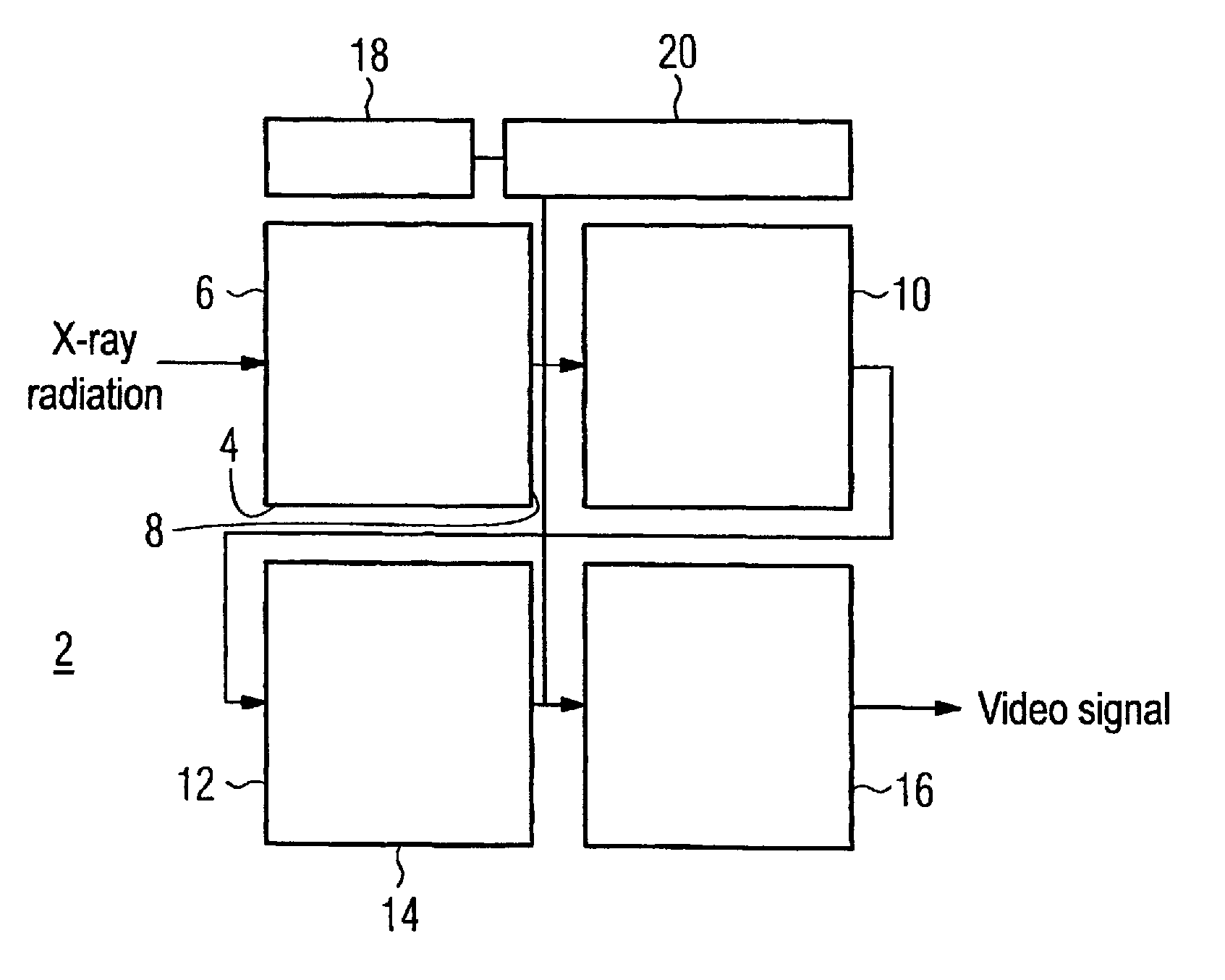
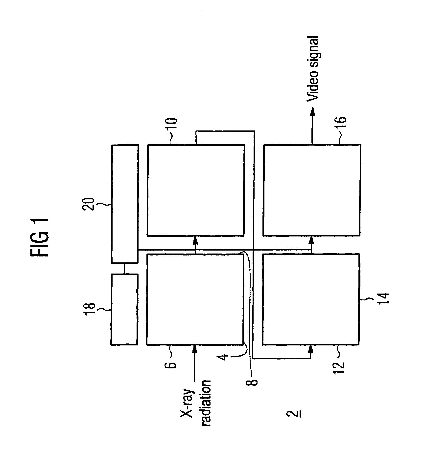
[0028]The x-ray image intensifier system 2 schematically depicted in FIG. 1 is a component of a medical x-ray diagnostic system (otherwise not additionally shown here). The x-ray image intensifier system 2 comprises an image converter tube 4 (also designated more concisely as an image converter or image intensifier). The image converter tube 4 in its simplest form comprises an entrance window 6 effective as a photocathode, from which the incident x-ray radiation releases electrons upon operation. Within the evacuated image converter tube 4, the electrons released in this way are accelerated via a high voltage applied between the cathode and an associated anode, and possibly are multiplied via a microchannel plate or the like (secondary electron multiplication). The electrons accelerated in this manner finally strike a luminescent screen 8 at the output side. An electro-optical mapping of the spatial intensity distribution of the x-ray radiation striking the input window 6 to the lum...


PUM


Abstract

An image intensifier system has an image converter tube to convert incident x-ray radiation into visible light and a digital camera system optically downstream of the image converter tube. The camera system has an image sensor to convert the incident, visible light into digital images, and an electronic image processing unit is provided for post-processing of the digital images. In such a system and a method for correcting image distortion errors that occur therein, characteristic data of a magnetic field present in the image converter tube are determined with the aid of a magnetic field probe arranged within the image converter tube or in its environment, an imaging error resulting from the presence of the magnetic field is quantitatively defined using the determined characteristic data, one or more parameters of a correction map leading to the correction of the imaging error are determined based on this, and the correction map that is established in this way is applied to the digital images in the electronic image processing unit.

Description

BACKGROUND OF THE INVENTION[0001]1. Field of the Invention[0002]The invention concerns a method to correct imaging errors (in particular distortions) in an x-ray image intensifier system of the type having an image converter tube to convert incident x-ray radiation into visible light and a digital camera system that is optically downstream of the image converter tube, wherein the camera system has an image sensor to convert the incident visible light into digital images, and wherein an electronic image processing unit is provided for post-processing the digital images. The invention furthermore concerns an associated x-ray image intensifier system.[0003]2. Description of the Prior Art[0004]An x-ray image intensifier is preferably used in medical x-ray diagnostics, as well as in materials testing. It converts x-ray radiation incident in an electron tube (also designated as an image converter tube, shortened to image converter or image intensifier) into visible light and amplifies the...

Claims


Application Information

Patent Timeline
IPC IPC(8): G01D18/00
CPCG03B42/02H04N5/3572H04N5/32H04N23/30
Inventor BEHRENS, RALFHANNEMANN, THILO
Owner SIEMENS AG
Why Eureka
Try Eureka