Viewing angle controlling liquid crystal panel and display device

a technology of liquid crystal panel and viewing angle, which is applied in non-linear optics, instruments, optics, etc., can solve the problems of insufficient image cannot be seen even in normal line direction, and image shielding against oblique view inevitably becomes insufficien

Active Publication Date: 2010-03-11
SHARP KK
View PDF12 Cites 4 Cited by
  • Summary
  • Abstract
  • Description
  • Claims
  • Application Information

AI Technical Summary

Benefits of technology

[0056]According to the above arrangement, no twisted component or few twisted components is contained in alignment of the liquid crystal molecules. In other words, the liquid crystal molecules are not in twisted alignment. This easily allows the polarization axis of the linearly polarized light having entered the liquid crystal layer to be parallel to the polarization axis of the linearly polarized light having exited from the liquid crystal layer.
[0057]Further, it becomes difficult that the liquid crystal molecules are tilted in directions other than a thickness direction of the liquid crystal layer. Further, the direction in which the liquid crystal molecules are tilted due to voltage application can be easily made parallel to or perpendicular to the polarization axis of the linearly polarized light having entered the liquid crystal layer.
[0058]In the viewing angle controlling liquid crystal panel of the present invention, it is preferable that the two or more areas into which the electrode is divided partially overlap with each other via an insulating layer so that no gap is produced between the two or more areas of the electrode in a plane view.
[0059]According to the above arrangement, the electrode for applying a voltage to the liquid crystal layer has no gap. Accordingly, a gap in shielding is hard to occur when the screen is viewed in the oblique direction.

Problems solved by technology

However, a conventional structure described in Patent Literature 1 has a problem in that shielding against a view in an oblique direction is not sufficient.
In a case where the entire screen is shielded, however, an image cannot be seen even in the normal line direction.
When an image is shielded against a view in the oblique direction while the image is kept visible with respect to a view in the normal direction, the shielding of the image against a view in the oblique direction inevitably becomes insufficient.

Method used


Image

  • Viewing angle controlling liquid crystal panel and display device
  • Viewing angle controlling liquid crystal panel and display device
  • Viewing angle controlling liquid crystal panel and display device

Examples


embodiment 1

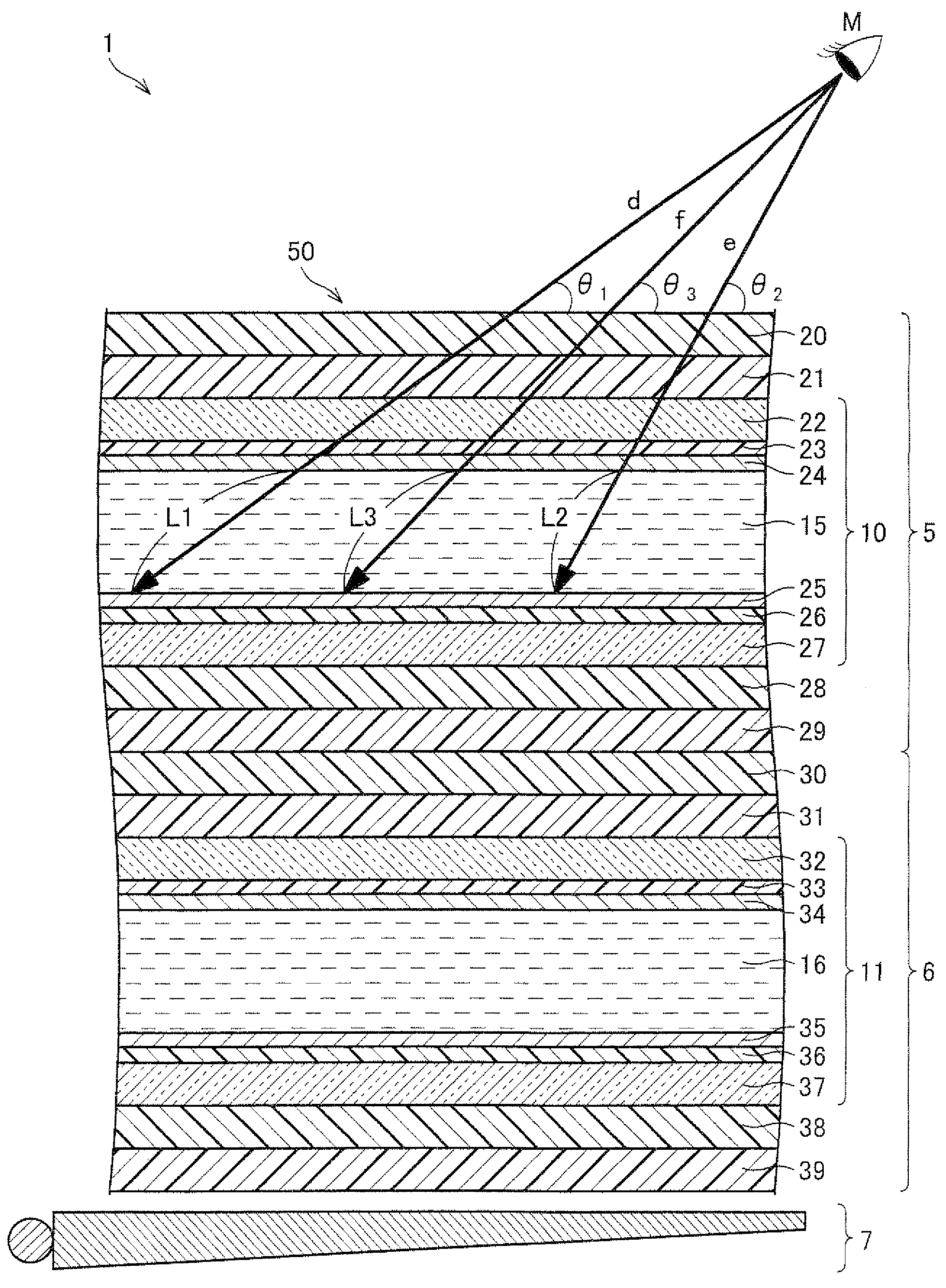
[0116]The following explains an embodiment of the present invention with reference to FIG. 1 through FIG. 3, showing as an example a liquid crystal display device 1 including a liquid crystal display panel 6 as a display panel.

(Cross Section Arrangement)

[0117]A schematic arrangement of the liquid crystal display device 1 of the present embodiment is substantially the same as an arrangement of a liquid crystal display device explained with reference to FIG. 9. Schematically, the liquid crystal display device 1 includes a viewing angle controlling liquid crystal panel 5, a liquid crystal display panel 6, and a backlight 7. Each of the viewing angle controlling liquid crystal panel 5 and the liquid crystal display panel 6 has the same arrangement as an arrangement of a typical liquid crystal panel. Namely, a liquid crystal layer (a first liquid crystal layer 15 or a second liquid crystal layer 16) is sandwiched between substrates (a first upper substrate 22 and a first lower substrate ...

embodiment 2

[0155]The following explains another embodiment of the present invention with reference to FIG. 4. FIG. 4 illustrates another embodiment of the present invention and is a diagram illustrating an electrode wiring pattern of a viewing angle controlling liquid crystal panel.

[0156]Note that an arrangement other than an arrangement explained in the present embodiment is the same as an arrangement in Embodiment 1. For convenience of explanation, members that have identical functions to those of members described in Embodiment 1 are given the same reference signs, and the explanations thereof are omitted.

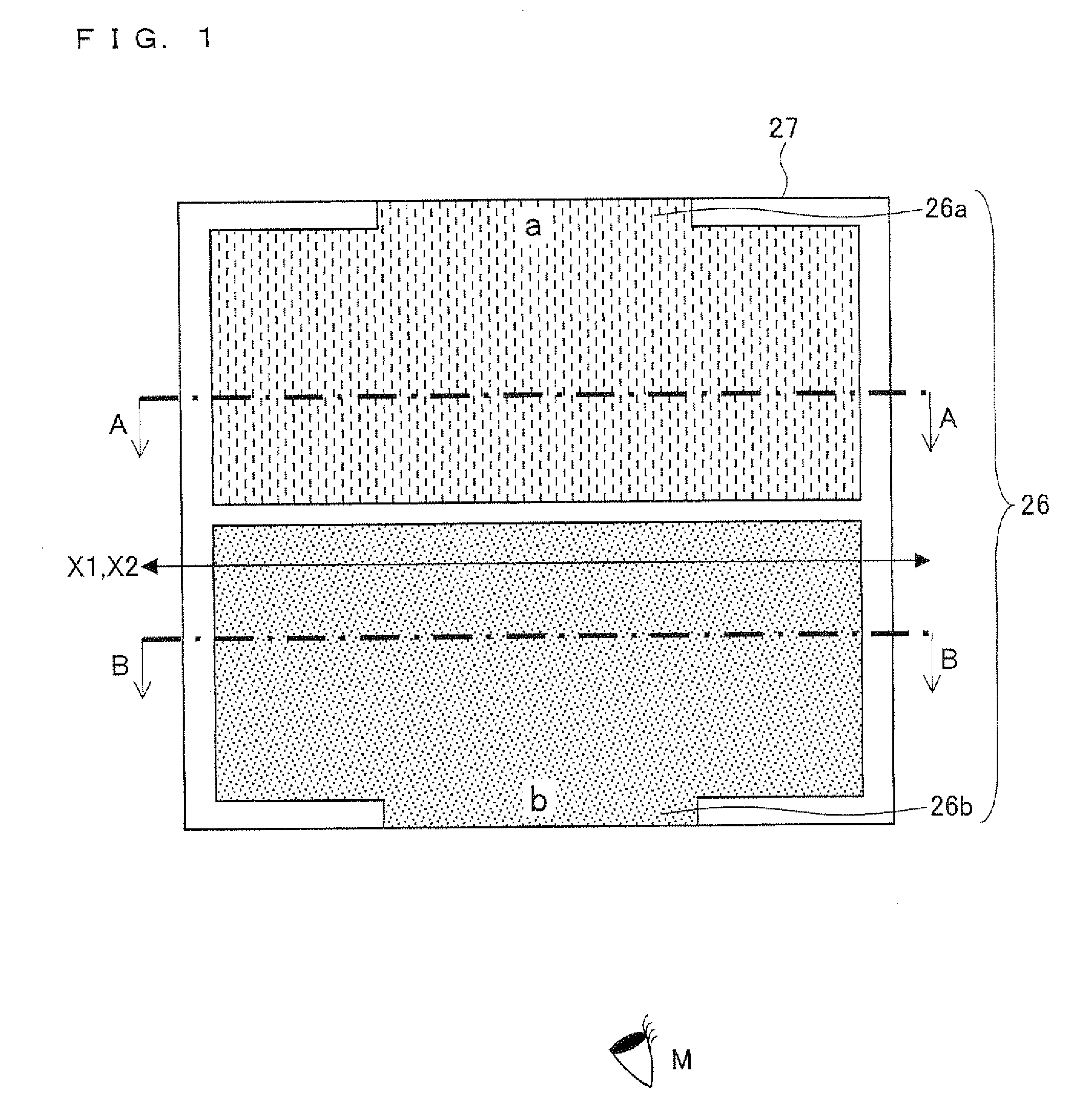
[0157]In a viewing angle controlling liquid crystal panel 5 according to the present embodiment, a pattern for dividing a first lower electrode 26 is different from a pattern in Embodiment 1. In other words, whereas, in Embodiment 1, due to the pattern for dividing the first lower electrode 26, the first lower electrode 26 is divided into two equal sections along a line in the vicinity of ...

embodiment 3

[0160]The following explains still another embodiment of the present invention with reference to FIG. 5, (a) of FIG. 6, and (b) of FIG. 6. FIG. 5 illustrates still another embodiment of the present invention and is a diagram illustrating an electrode wiring pattern of the viewing angle controlling liquid crystal panel. (a) of FIG. 6 is a cross sectional view taken from a line C-C in FIG. 5. Further, (b) of FIG. 6 illustrates another example of a cross section of the first lower substrate. (b) of FIG. 6 is a cross sectional view equivalent to the cross sectional view taken from the line C-C in FIG. 5.

[0161]Note that an arrangement other than an arrangement explained in the present embodiment is the same as arrangements in the above embodiments. For convenience of explanation, members that have identical functions to those of the members in the embodiments described above are given the same reference signs and explanations thereof are omitted.

[0162]The viewing angle controlling liquid...


PUM

PropertyMeasurementUnit
viewing angleaaaaaaaaaa
voltageaaaaaaaaaa
voltagesaaaaaaaaaa

Abstract

A viewing angle controlling liquid crystal panel in which uniformity of a shielding effect in a screen is further improved is provided. Linearly polarized light enters a liquid crystal layer. Further, the liquid crystal layer is provided, on a light exit side of the liquid crystal layer, with a polarizing plate transmitting only a component of light having exited from the liquid crystal layer which component is parallel to a polarization axis of the linearly polarized light having entered the liquid crystal layer. Liquid crystal molecules contained in the liquid crystal layer are tilted in a direction parallel to or perpendicular to the polarization axis of the linearly polarized light having entered the liquid crystal layer. In addition, an electrode (26) is provided so that two or more different voltages can be applied to the liquid crystal layer simultaneously.

Description

TECHNICAL FIELD[0001]The present invention relates to a viewing angle controlling liquid crystal panel which controls a viewing angle of a display panel and a display device including a display panel and the viewing angle controlling liquid crystal panel.BACKGROUND ART[0002]Generally, display devices are required to have a viewing angle as wide as possible so that an image can be seen sharply from any visual angles. In particular, in liquid crystal display devices which are prevalent in these years, because a refractive index of a liquid crystal molecule has dependency on visual angles, various techniques have been developed for widening the viewing angle. Note that (i) the visual angle indicates an angle between a screen of a display device and a direction in which the screen is viewed; and (ii) the viewing angle indicates an angular range in which a certain display quality can be obtained.[0003]Depending on an environment in which a display device is used, however, it may be prefe...

Claims


Application Information

Patent Timeline
Patent Type & Authority Applications(United States)
IPC IPC(8): G02F1/1347G02F1/1335
CPCG02F1/1323G02F1/133528G02F2201/122G02F1/13471G02F1/137G02F1/134309
Inventor SAKAI, TAKEHIKOCHIBA, DAIMORISHITA, KATSUHIKOKATAOKA, YOSHIHARUTSUKAMURA, CHIKANORI
Owner SHARP KK
Why Eureka
Try Eureka