
Connector bracket for a semitrailer of a semitrailer truck

a technology for connecting brackets and semi-trailers, which is applied in the direction of tractor-trailer combinations, electric/fluid circuits, towing devices, etc., can solve the problems of aggravated problems, plug-in devices can also be disabled, and the connection at the semi-trailer is open in the driving direction and subject to considerable dirt and grime, etc., to achieve the effect of accelerating corrosion

Active Publication Date: 2010-03-11
JOST WERKE
View PDF7 Cites 8 Cited by
  • Summary
  • Abstract
  • Description
  • Claims
  • Application Information

AI Technical Summary

Benefits of technology

[0007]A major benefit of the invented connector bracket is that the connector can travel mechanically between the standby position and the coupling position. Therefore, it is not necessary to provide a self-sufficient power supply for the semitrailer or to install additional servo motors on the semitrailer. Since the support element is adapted to the ISO contour of the insertion opening, semitrailers outfitted with the connector bracket can be hooked up without problem by tractor vehicles with conventional supply lines plugged in by hand.
[0027]The locking of the connector in the socket is preferably free of play, in order to prevent movements and thus an accelerated corrosion after contact has been made.

Problems solved by technology

The major drawback of this known system is that the connector at the semitrailer is open in the driving direction and subjected to considerable dirt and grime during the drive.
This problem is further aggravated when semitrailers outfitted with the known plug-in device are used in a mixed fleet whose tractor vehicles are outfitted with a socket not yet designed complementary to the connector, for then solids swirled up by the tractor can get into the connector pointing opposite the driving direction.
In the winter months, the plug-in device can also become disabled by ice build-up.

Method used


Image

  • Connector bracket for a semitrailer of a semitrailer truck
  • Connector bracket for a semitrailer of a semitrailer truck
  • Connector bracket for a semitrailer of a semitrailer truck

Examples


Embodiment Construction

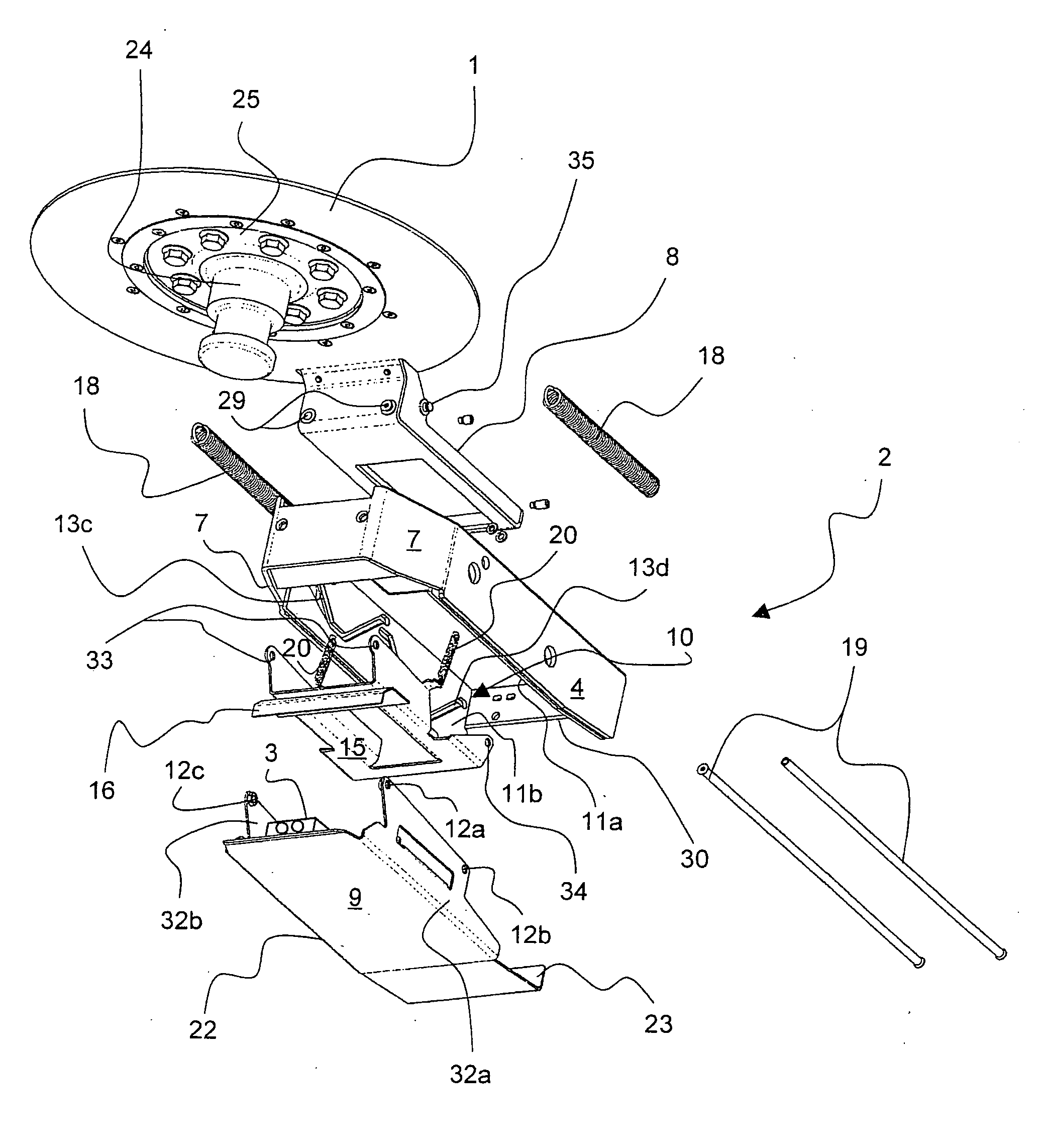
[0043]FIG. 1 shows a three dimensional bottom view of exploded components of the connector bracket of the invention. The support element 2 engages by means of a rigid support frame 8 with a bearing 1 and can thereby swivel on the underside of a semitrailer, not shown. The bearing 1 concentrically surrounds a king pin 24. The king pin 24 is screwed torsion-free against the bottom side of the semitrailer by a fastening disk 25.

[0044]A casing frame 4 is fastened to the support frame 8 and it can move in the horizontal direction. The horizontal movability is accomplished by two parallel guide rails 19, running through the casing frame 4 in the lengthwise direction, being fashioned as cylindrical rods and being guided by a slide bearing 29 for each on the support frame 8.

[0045]When there is no fifth wheel 6 present (see FIG. 4), the casing frame 4 is held in its forward position by two casing return springs 18, that is, at a slight distance from the king pin 25. The casing return springs...


PUM


Abstract

The invention relates, inter alia, to a connector bracket for a semitrailer of a semitrailer truck. Said connector bracket comprises a support element which can be swiveled about a bearing and a connector arranged inside the support element, the support element having a casing frame with a section that is complementary to an insertion opening of a fifth wheel. The aim of the invention is to provide a connector bracket or a plug-in coupling which is highly reliable even under adverse external conditions. This aim is achieved, inter alia, by the connector bracket according to the invention, wherein the casing frame can be displaced in relation to the connector by contact with the insertion opening, thereby displacing the connector from a closed standby position to an open coupling position.

Description

FIELD OF INVENTION[0001]The invention concerns a connector bracket for a semitrailer of a semitrailer truck, comprising a support element which can swivel about a bearing and a connector arranged in the support element, the support element having a casing frame with a segment shaped complementary to an insertion opening of a fifth wheel. Furthermore, the invention is also implemented on a plug-in coupling system.BACKGROUND OF THE INVENTION[0002]Such connector brackets and plug-in coupling systems are used on semitrailer trucks, after a mechanical coupling of the semitrailer, to also connect the supply lines of the tractor vehicle to the semitrailer in largely automated fashion, so that the driver no longer has to climb between the tractor and the semitrailer and plug in the connection lines there, such as for the compressed air and electricity supply, by hand.[0003]One prior art of this kind is disclosed by DE 10 2004 024 333 A1 with a plug-in coupling system, in which a plug-in dev...

Claims


Application Information

Patent Timeline
Patent Type & Authority Applications(United States)
IPC IPC(8): B60D1/62
CPCB60D1/363B62D53/125B60D1/62
Inventor ALGUERA, JOSE MANUELEIERMANN, MICHAELRICHTER, MARTIN
Owner JOST WERKE
Learn More