
Externally adjustable blood flow valve

Inactive Publication Date: 2010-03-04
MACHAN LINDSAY +1
View PDF13 Cites 15 Cited by
  • Summary
  • Abstract
  • Description
  • Claims
  • Application Information

AI Technical Summary

Benefits of technology

[0003]A valve installed in a blood vessel can be externally adjusted over a wide range of flow rates. Such a valve can be incorporated in an AV shunt or AV fistula to allow large flow during dialysis and small flow at all other times. The valve can be activated by finger pressure, hypodermic needle or by an electromagnetic field. The valve is shaped like a Venturi tube with round cross section and smooth diameter transition to minimize blood damage and clotting. Hemodynamic properties are further enhanced by keeping the part coming in contact with the blood a single continuous tubing.

Problems solved by technology

During dialysis it is desired to have a large blood flow from the artery to the vein but in the period between dialysis sessions such a large flow damages the veins, as the operate at a much lower blood pressure.
Prior art valves suggested for AV shunts had a sudden change in cross section and also had pockets of very low blood flow, causing clotting.
When a tube is squeezed the cross section does not stay round, causing spots with low blood flow which generate blood clots.

Method used


Image

  • Externally adjustable blood flow valve
  • Externally adjustable blood flow valve
  • Externally adjustable blood flow valve

Examples


Embodiment Construction

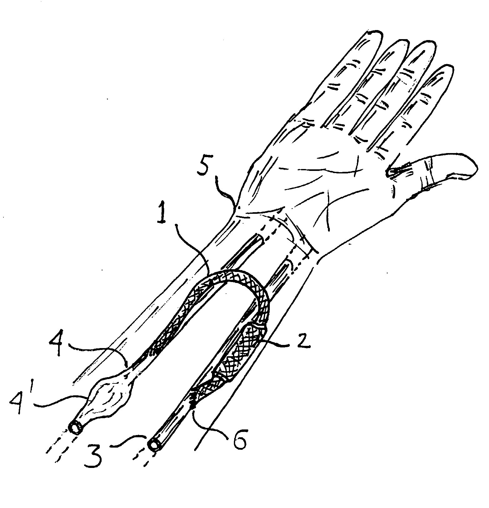
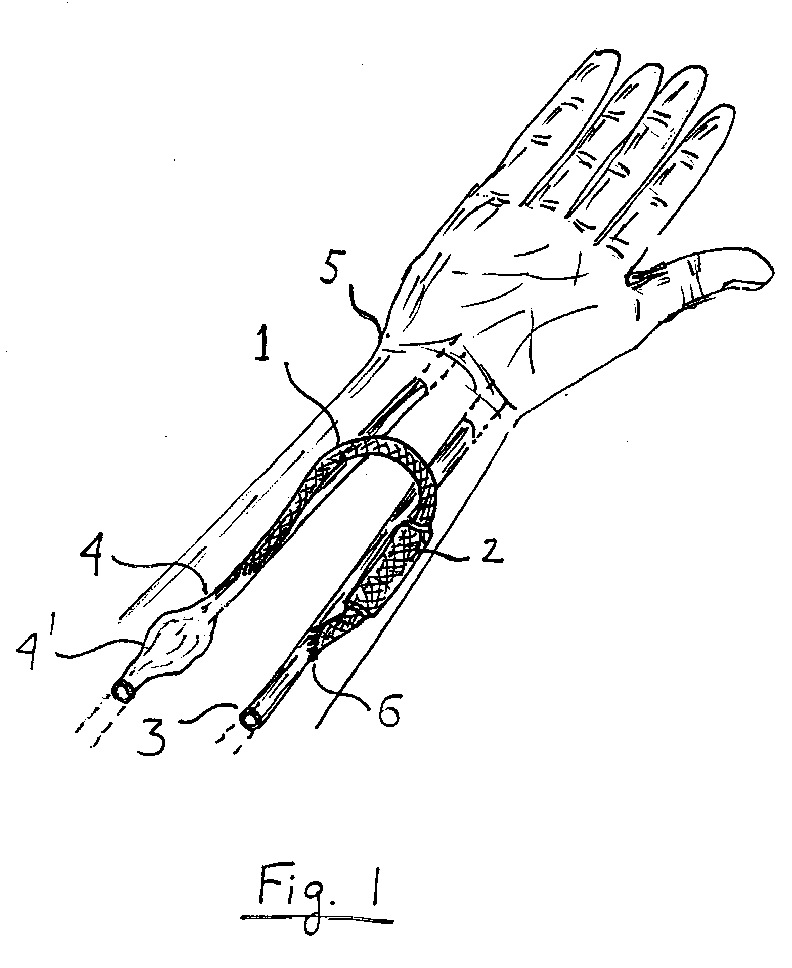
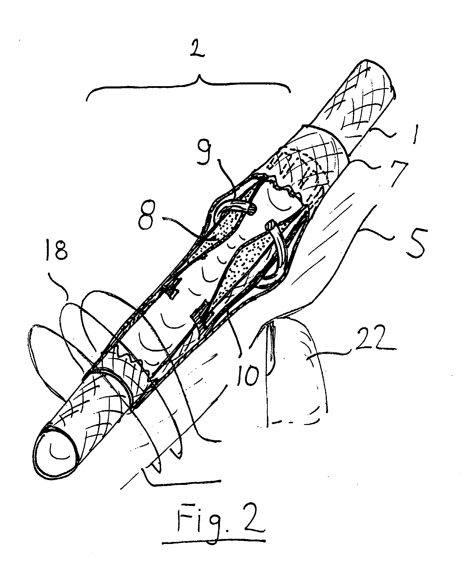
[0013]Referring to FIG. 1, an AV shunt 1 connects artery 3 to vein 4 in arm 5 via valve 6. Prior art AV shunts do not include valve 2. During dialysis hypodermic needles are placed in shunt 1 or fistula 4′ formed in the vein. The shunt 1 can be replaced by a direct connection between artery 3 and vein 4. In such a case the valve 2 is installed in the connection. The art of Av fistulas and shunts is well known and need not be further detailed. Valve 2 allows full blood flow during dialysis and restricts blood flow at all other times. The valve can be controlled is several ways, some of the preferred ways are listed here:[0014]A. Direct mechanical control, by sliding or moving part of the valve that can be felt from outside of the body. For example, when installed in the arm, a ring can be caused to slide inside the valve by pushing the tissue above it.[0015]B. Hydraulic control. Injecting or removing a fluid from a section of the valve by using a hypodermic needle controls the flow.[...


PUM


Abstract

A valve installed in a blood vessel can be externally adjusted over a wide range of flow rates. Such a valve can be incorporated in an AV shunt or AV fistula to allow large flow during dialysis and small flow at all other times. The valve can be activated by finger pressure, hypodermic needle or by an electromagnetic field. The valve is shaped like a Venturi tube with round cross section and smooth diameter transition to minimize blood damage and clotting. Hemodynamic properties are further enhanced by keeping the part coming in contact with the blood a single continuous tubing.

Description

FIELD OF THE INVENTION [0001]The invention is in the medical field and in particular in the field of Arteriovenous Shunts and Fistulas, also known as AV shunts and AV fistulas, used in dialysis.BACKGROUND OF THE INVENTION [0002]A significant number of patients suffering from kidney failure require periodic dialysis. In order to speed up the pumping of the blood through the dialysis machine, a fistula is formed, typically in the arm, by connecting the main artery to the vein. The connection can be by cutting the two walls and suturing them together or by using a short graft to connect them. The graft can be made from a blood vessel taken from the patient or made from an artificial material such as Gortex (PTFE fabric), polyurethane or silicone rubber. Such a fistula or graft allows the repeated piercing by a hypodermic needle required by the dialysis process. During dialysis it is desired to have a large blood flow from the artery to the vein but in the period between dialysis sessio...

Claims


Application Information

Patent Timeline
IPC IPC(8): A61M1/00
CPCA61M1/3655A61M2205/0266A61M2205/8243A61M2205/3515A61M2205/353A61M2205/04
Inventor MACHAN, LINDSAYGELBART, DANIEL
Owner MACHAN LINDSAY
Learn More