Eureka AIR delivers breakthrough ideas for toughest innovation challenges, trusted by R&D personnel around the world.

Image processing apparatus, image processing method, and image processing program

Active Publication Date: 2010-03-04
138 EAST LCD ADVANCEMENTS LTD
View PDF8 Cites 27 Cited by
  • Summary
  • Abstract
  • Description
  • Claims
  • Application Information

AI Technical Summary

Benefits of technology

[0007]An advantage of some aspects of the invention is to provide an image processing apparatus, an image processing method, and an image processing program each of which makes it possible to easily obtain a deformed image that looks nice as a result of the deformation of an original image containing a person.
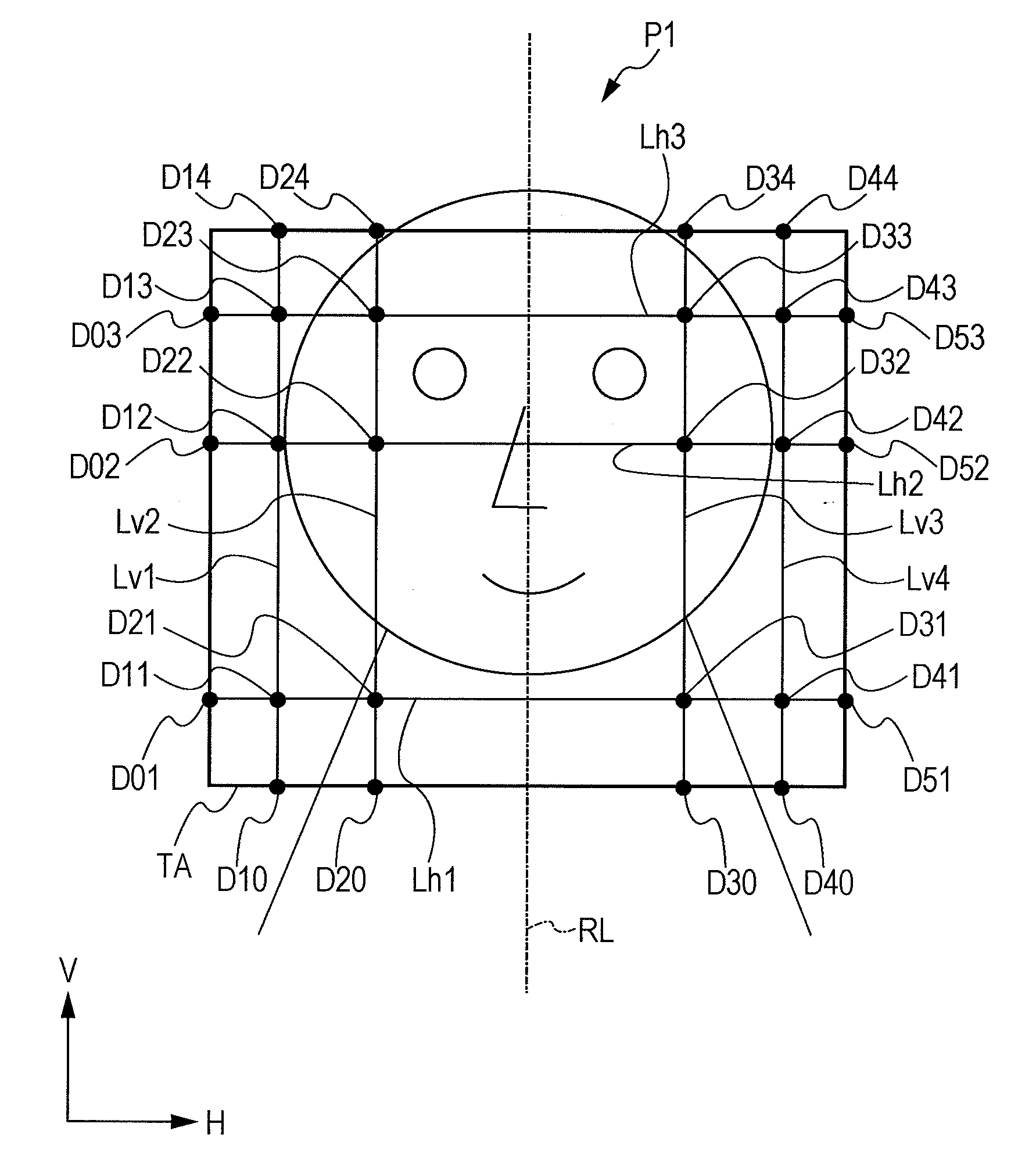
[0009]The image processing apparatus may further include an instruction receiving section that receives an instruction given from the outside for making a face look smaller. In such a configuration, the face deforming section may reduce expansion amount that is applied to at least a part of the face image mentioned above when the instruction receiving section has received the instruction. With such a preferred configuration, it is possible to obtain such a processed image including the compressed area that gives no sense of strangeness or unnaturalness to a user. In addition, the size of a face in the processed image is reduced moderately.
[0010]The face deforming section may determine the expansion amount on the basis of a value that is calculated as a predetermined percentage of a value of the compression rate. For example, if the value of the compression rate is 20%, the face deforming section may set a certain percentage (i.e., ratio) of the value of the compression rate as the expansion amount. As described above, instead of using expansion amount that is too large to completely offset the effects of the compression of a compression area for the expansion of a face image, the amount of expansion of the face image is determined on the basis of a value that is calculated as a predetermined percentage of a value of the compression rate. By this means, as a result of the processing of the image deforming section and the processing of the face deforming section, it is possible to obtain a processed image having an optimum balance between the size of a face and the size of a body in the compressed area.
[0011]The face deforming section may determine compression amount on the basis of a value that remains after subtracting the predetermined percentage value from the value of the compression rate and then deform the face image by the determined compression amount so as to compress at least a part of the face image in a direction orthogonal to the specific direction. With such a preferred configuration, the face image is expanded in the specific direction and compressed in the direction orthogonal to the specific direction. By this means, as a result of the processing of the image deforming section and the processing of the face deforming section, it is possible to obtain a processed image having an optimum balance between the size of a face and the size of a body in the compressed area.
[0013]The area setting section may divide the target image into the compression area and an area excluding the compression area with the use of a line orthogonal to the specific direction. With such a preferred configuration, when the image of a person is included in the compression area, it is possible to obtain a processed image that is not perceived by a user as strange or unnatural because the vertical-to-horizontal ratio of a face does not substantially change while slimming the body shape of the person moderately as a result of compression.

Problems solved by technology

However, if deformation processing is performed uniformly on an area of an image that contains a person, the face of the person will also be affected by the deformation processing.
If the ratio changes substantially, a user will feel that a processed person image is strange or unnatural even when the image represents a slim and slender figure as s / he desires.

Method used


Image

  • Image processing apparatus, image processing method, and image processing program
  • Image processing apparatus, image processing method, and image processing program
  • Image processing apparatus, image processing method, and image processing program

Examples


Embodiment Construction

[0035]In the following description, exemplary embodiments of the present invention are explained in order to clarify the technical concepts thereof summarized as above. The embodiments of the invention are organized into the following three sections in this specification.

[0036]1. Overall Configuration of Image Processing Apparatus

[0037]2. Image Correction Processing

[0038]3. Another Embodiment

1. Overall Configuration of Image Processing Apparatus

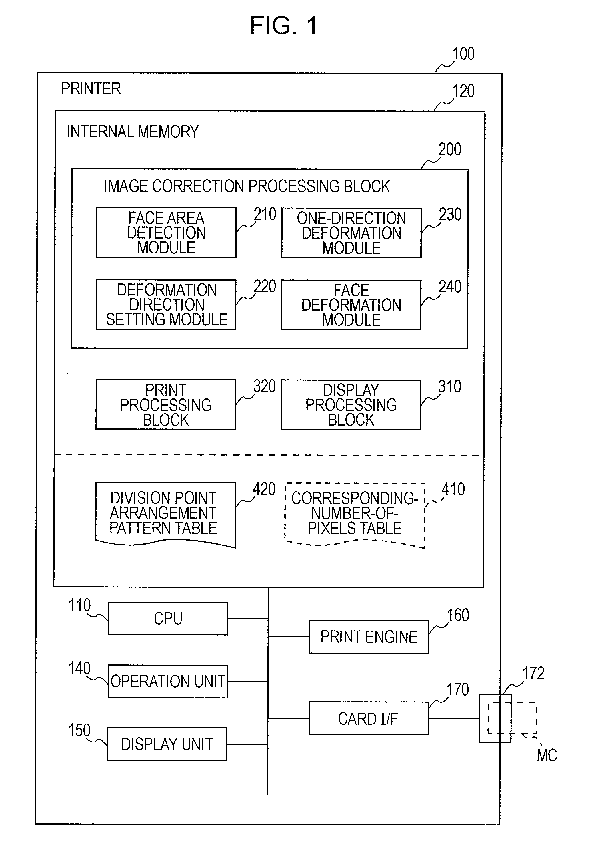
[0039]FIG. 1 is a diagram that schematically illustrates an example of the configuration of a printer 100, which is an example of an image processing apparatus according to an exemplary embodiment of the invention. The printer 100 is a color ink jet printer having a so-called direct print capability. As a direct-printing device, the printer 100 outputs a print image on the basis of image data read out of a storage medium such as a memory card MC or the like. The printer 100 is provided with an internal memory 120, a CPU 110, an operation unit...


PUM


Abstract

An image processing apparatus includes an area setting unit, an image deformation unit, and a face deformation unit. The area setting unit sets, in a target image that includes a face image, an area including the face image as a compression area. The image deformation unit compresses the compression area in a specific direction at a predetermined compression rate. The face deformation unit deforms the face image by expansion amount determined on the basis of the compression rate in such a manner that at least a part of the face image is expanded in the specific direction.

Description

[0001]Priority is claimed under 35 U.S.C. §119 to Japanese Application No. 2008-217922 filed on Aug. 27, 2008, which is hereby incorporated by reference in its entirety.BACKGROUND[0002]1. Technical Field[0003]The present invention relates to an image processing apparatus, an image processing method, and an image processing program.[0004]2. Related Art[0005]An image processing technique for deforming an image such as a digital image is known. For example, an image processing technique for deforming a face is disclosed in JP-A-2004-318204. In the image processing technique disclosed in JP-A-2004-318204, a partial area on the image of a face (an area of a cheek image) is set as a correction area. The correction area is segmented into a plurality of sub areas in accordance with a predetermined pattern. Then, an image is expanded or compressed with a scaling factor that is set for each sub area. As a result, the face is deformed.[0006]When an image contains a person including a face, a u...

Claims


Application Information

Patent Timeline
IPC IPC(8): G06K9/36
CPCG06T3/0093G06T3/18
Inventor KOBAYASHI, AYAKO
Owner 138 EAST LCD ADVANCEMENTS LTD
Why Eureka
Eureka Blog
Learn More