
Camera module

a technology of camera module and camera body, applied in the field of camera module, can solve problems such as misalignment of optical axis, and achieve the effect of improving movement accuracy and driving reliability

Active Publication Date: 2010-03-04
SAMSUNG ELECTRO MECHANICS CO LTD
View PDF7 Cites 34 Cited by
  • Summary
  • Abstract
  • Description
  • Claims
  • Application Information

AI Technical Summary

Benefits of technology

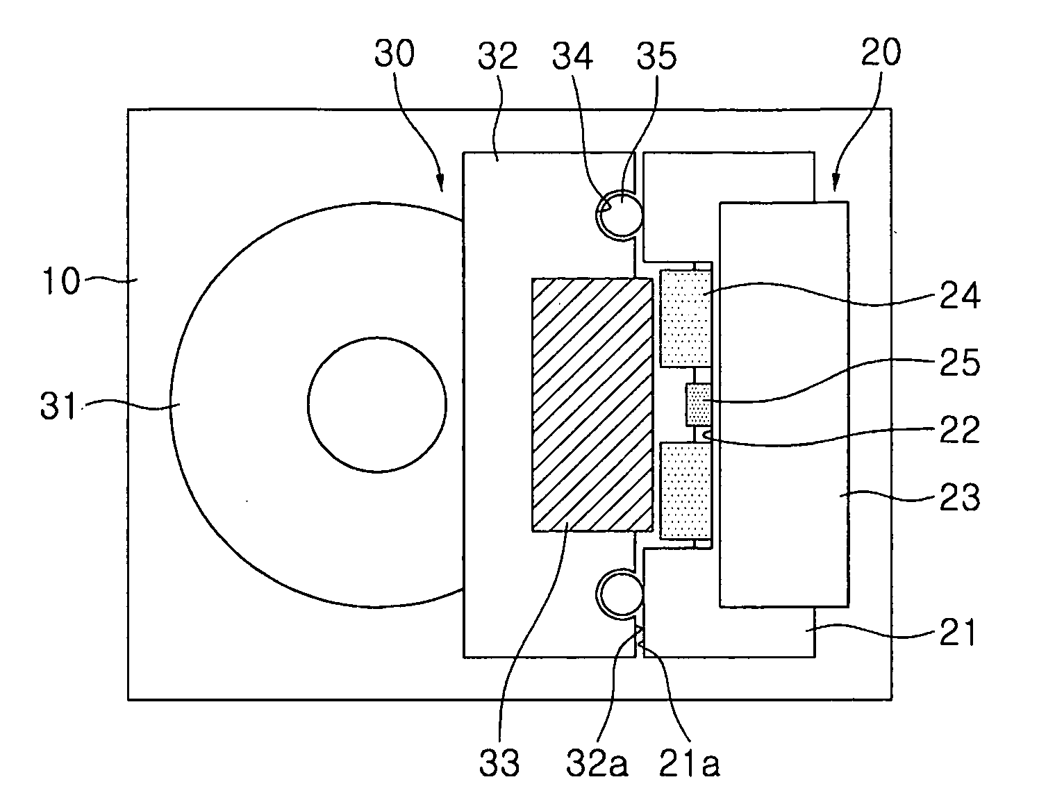
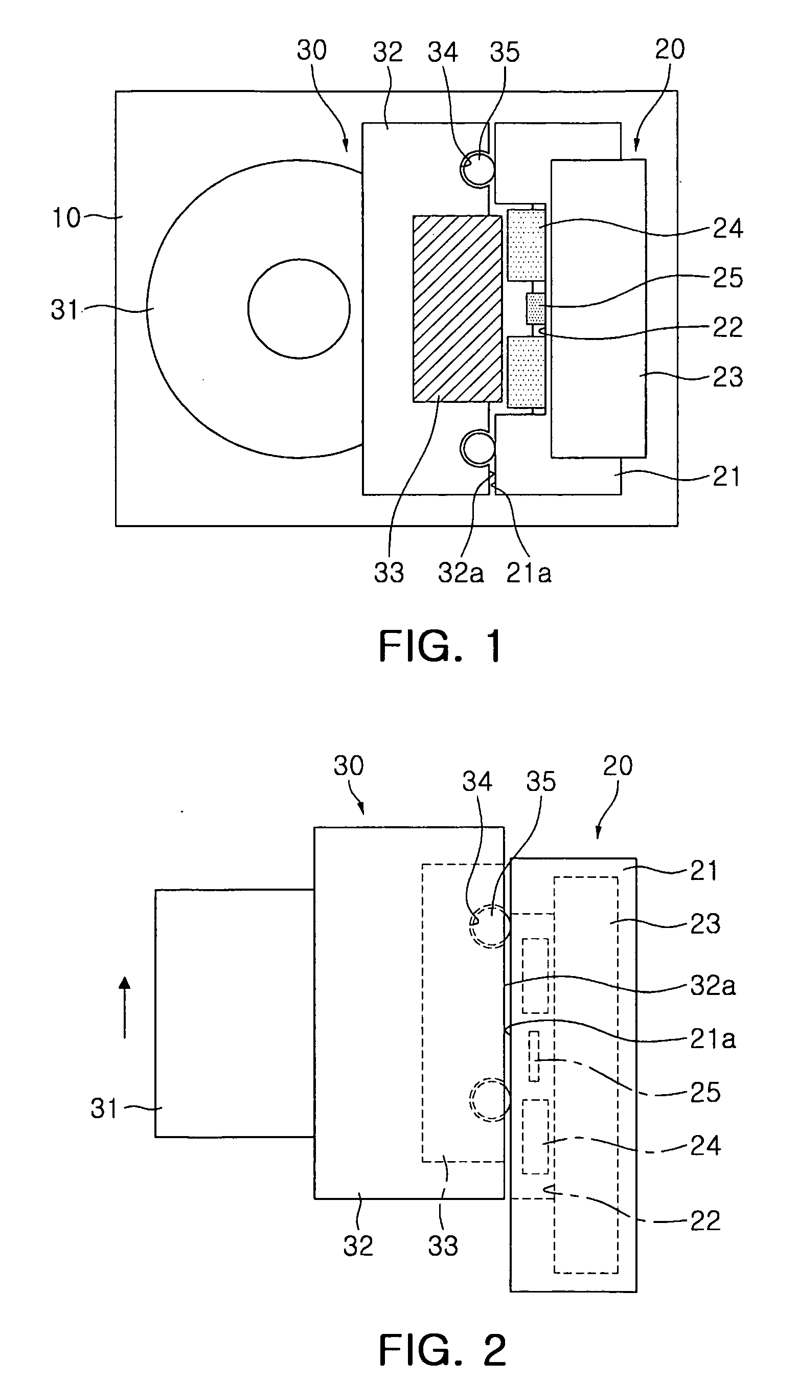
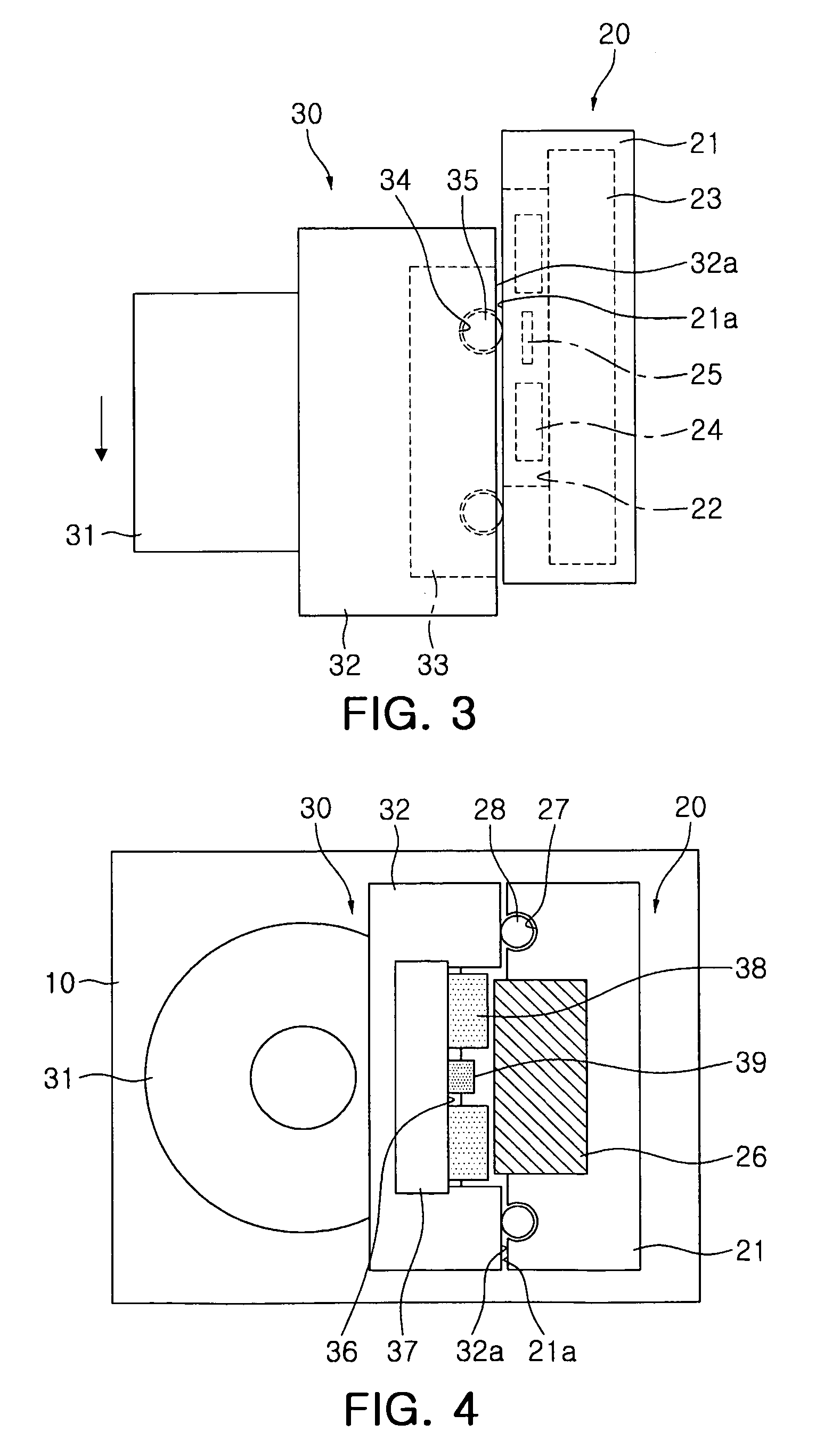
[0012]An aspect of the present invention provides a camera module that can improve movement accuracy and driving reliability when performing autofocus and zoom by using a structure providing a force to reliably support a lens barrel to correct an error caused when driving the lens barrel.

Problems solved by technology

However, the reduction in strength of the elastic member causes serious problems, such as a dropping of the lens barrel and misalignment of the optical axis.

Method used


Image

  • Camera module
  • Camera module
  • Camera module

Examples


Embodiment Construction

[0026]Exemplary embodiments of the present invention will now be described in detail with reference to the accompanying drawings.

[0027]The invention may however be embodied in many different forms and should not be construed as limited to the embodiments set forth herein. Rather, these embodiments are provided so that this disclosure will be thorough and complete, and will fully convey the scope of the invention to those skilled in the art.

[0028]The invention basically relates to a camera module that can move a lens module by a driving force generated by electromagnetic interaction between a magnet and a coil.

[0029]As the magnet generates a predetermined magnetic field, and a current flows through the coil across the magnetic fields, a predetermined force is applied according to Fleming's left-hand rule.

[0030]The force allows the camera module to perform autofocus and zoom while moving the lens module. This type of camera module is called a voice coil type actuator (VCA) camera modu...


PUM


Abstract

A camera module according to an aspect of the invention may include: a housing; a fixed unit fixed to the inside of the housing; a lens barrel provided in the housing and having at least one lens; and a moving unit moved and supported by the fixed unit by a predetermined magnetic force, and moving the lens barrel along an optical axis, such that driving accuracy and reliability can be increased when performing auto focus or zoom.

Description

CROSS-REFERENCE TO RELATED APPLICATIONS[0001]This application claims the priority of Korean Patent Application No. 2008-0086054 filed on Sep. 1, 2008, in the Korean Intellectual Property Office, the disclosure of which is incorporated herein by reference.BACKGROUND OF THE INVENTION[0002]1. Field of the Invention[0003]The present invention relates to camera modules, and more particularly, to a camera module that is provided in a camera device, such as a small electronic device.[0004]2. Description of the Related Art[0005]In general, camera modules are small in size, and have been applied to portable mobile communication apparatuses, such as camera phones, PDAs, and smart phones, and various types of IT equipment. Recently, as these apparatuses and equipment have been reduced in size, thickness, and weight, the size of the camera modules has been correspondingly reduced.[0006]This camera module is being manufactured, including an image sensor, such as a charge coupled device (CCD) or ...

Claims


Application Information

Patent Timeline
Patent Type & Authority Applications(United States)
IPC IPC(8): G02B7/09G02B7/04
CPCG02B7/102G03B17/00H01L27/146H04N23/00
Inventor KANG, SEONG HOBAIK, JAE HO
Owner SAMSUNG ELECTRO MECHANICS CO LTD
Learn More