Multi-Function Device
- Summary
- Abstract
- Description
- Claims
- Application Information
AI Technical Summary
Benefits of technology
Problems solved by technology
Method used
Image
Examples
first embodiment
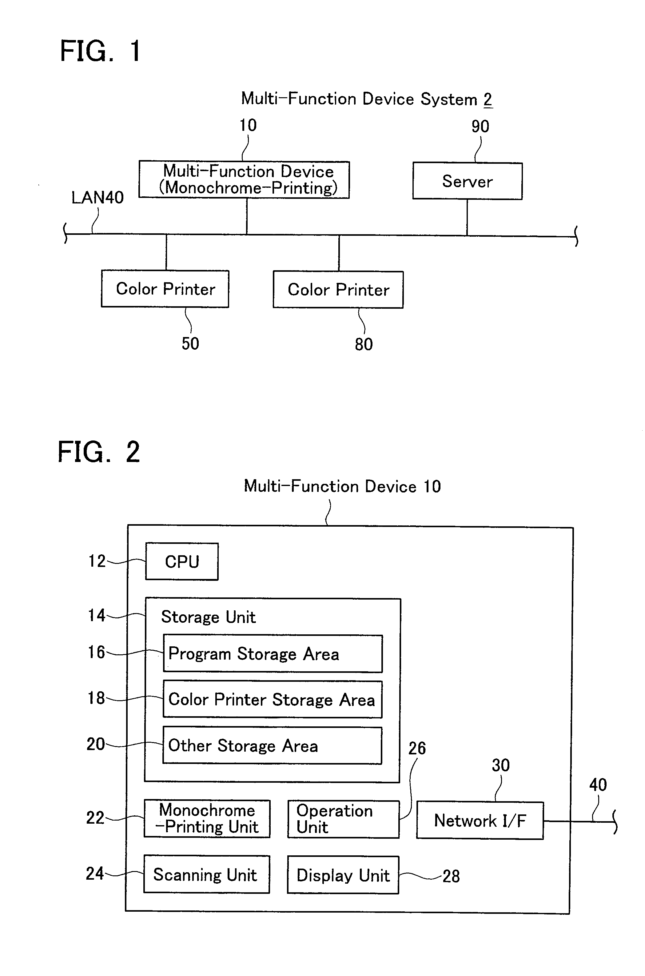
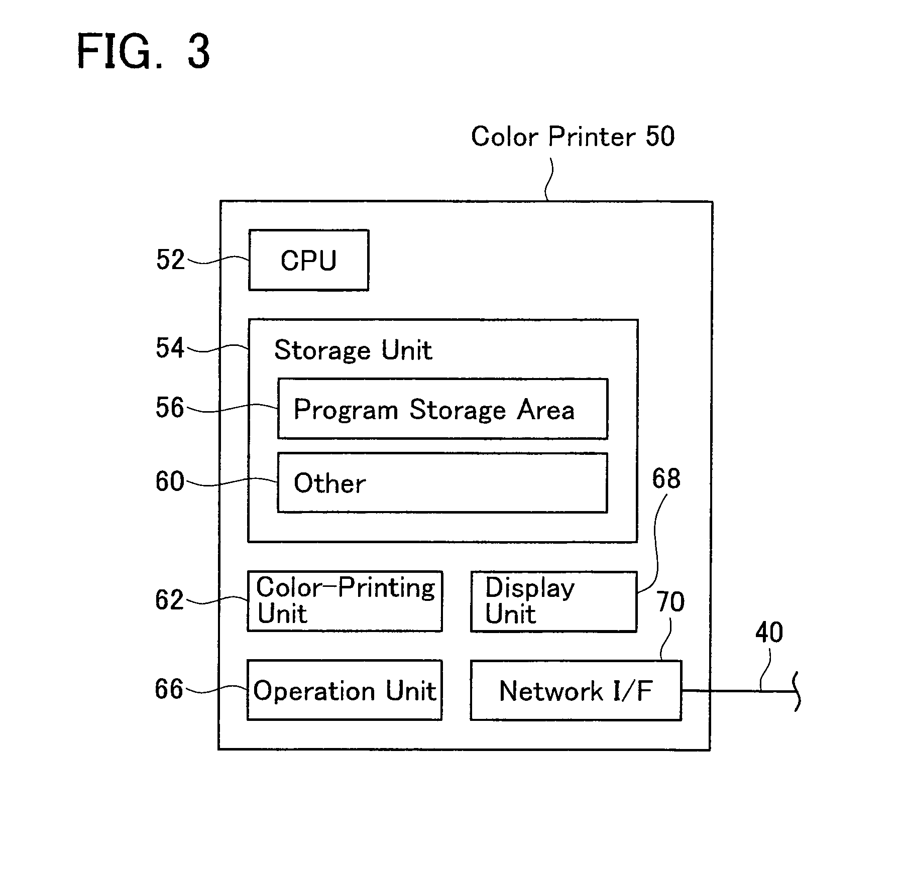
[0026]A first embodiment will be described with reference to the drawings. As shown in FIG. 1, the multi-function device system 2 comprises a multi-function device 10, a plurality of color printers 50, 80, and a server 90, etc. Each device 10, 50, 80, 90 is connected to a LAN 40. Each device 10, 50, 80, 90 can communicate with each other via the LAN 40. Next, configurations of the multi-function device 10 and the color printers 50, 80 are described below. Note that, a configuration of the server 90 will be described in the third embodiment.
(Configuration of Multi-Function Device)
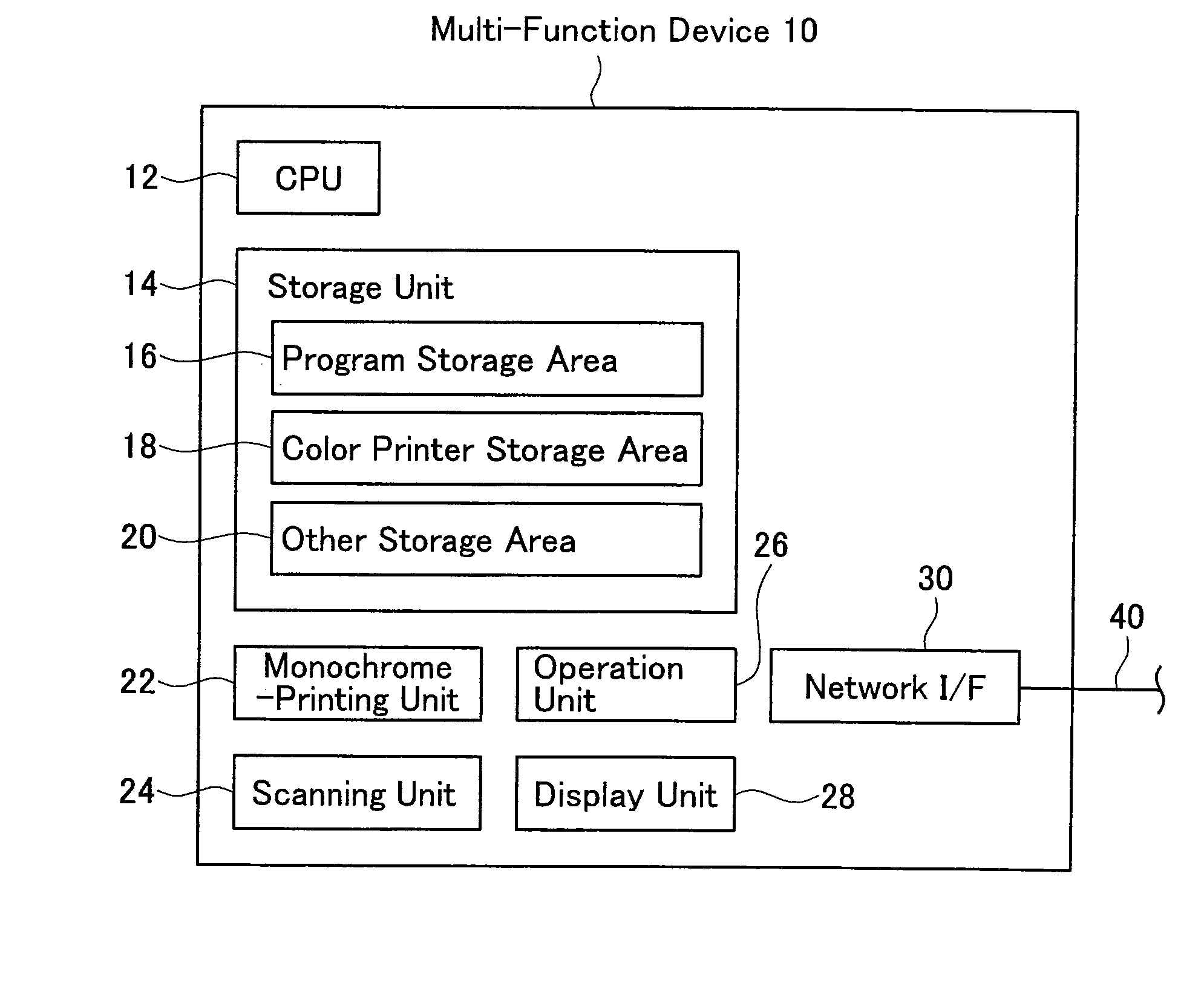
[0027]First, the configuration of the multi-function device 10 will be described. As shown in FIG. 2, the multi-function device 10 comprises a CPU 12, a storage unit 14, a monochrome-printing unit 22, a scanning unit 24, an operation unit 26, a display unit 28, and a network I / F 30, etc.
[0028]The CPU 12 executes various processes in accordance with programs stored in the storage unit 14. The processes execut...
second embodiment
[0042]Next, a second embodiment will be described. The parts different from the first embodiment will mainly be described. In this embodiment, a part of the color printer setting process executed by the multi-function device 10 is different from the first embodiment.
(Color Printer Setting Process Executed by Multi-Function Device)
[0043]FIG. 6 is a flowchart of the color printer setting process of this embodiment. The CPU 12 waits until an IP address is input by the user (S50). This step is equal to S10 of FIG. 4. Next, the CPU 12 sends a data format request command with the input IP address as a destination (S52). As will be described in detail later, the color printer (for example, the color printer 50), which has received the data format request command, sends a response including information related to the PDL data format which can be interpreted by the color printer itself. The CPU 12 monitors the reception of the response (S54). In a case where the response is not received even...
third embodiment
[0053]Next, a third embodiment will be described. The parts different from the first embodiment will mainly be described. In this embodiment, the multi-function device 10 obtains the IP addresses and the PDL data formats of the color printers 50, 80 using the server 90.
(Configuration of Server)
[0054]A configuration of the server 90 will be described. As shown in FIG. 8, the server 90 comprises a CPU 92, a storage unit 94, an operation unit 122, a display unit 124, and network I / F 126, etc.
[0055]The CPU 92 executes various processes in accordance with programs stored in the storage unit 94. The processes executed by the CPU 92 will be described in detail later. The storage unit 94 includes a program storage area 96, a device information storage area 98 and another storage area 120, etc. The program storage area 96 stores the programs to be executed by the CPU 92. The device information storage area 112 can store a plurality of items of association data 100, 102. Each item of the asso...
PUM
 Abstract
Description
Claims
Application Information
 - R&D
- Intellectual Property
- Life Sciences
- Materials
- Tech Scout
- Unparalleled Data Quality
- Higher Quality Content
- 60% Fewer Hallucinations
Browse by: Latest US Patents, China's latest patents, Technical Efficacy Thesaurus, Application Domain, Technology Topic, Popular Technical Reports.
© 2025 PatSnap. All rights reserved.Legal|Privacy policy|Modern Slavery Act Transparency Statement|Sitemap|About US| Contact US: help@patsnap.com


