Battery-powered occupancy sensor
a battery-powered occupancy sensor and occupancy sensor technology, applied in the direction of electric signalling details, wireless commuication services, instruments, etc., can solve the problems of increasing the likelihood that the load control device may not detect the presence of a user, and the control system requires advanced system components and configuration procedures in order to operate properly
- Summary
- Abstract
- Description
- Claims
- Application Information
AI Technical Summary
Benefits of technology
Problems solved by technology
Method used
Image
Examples
first embodiment
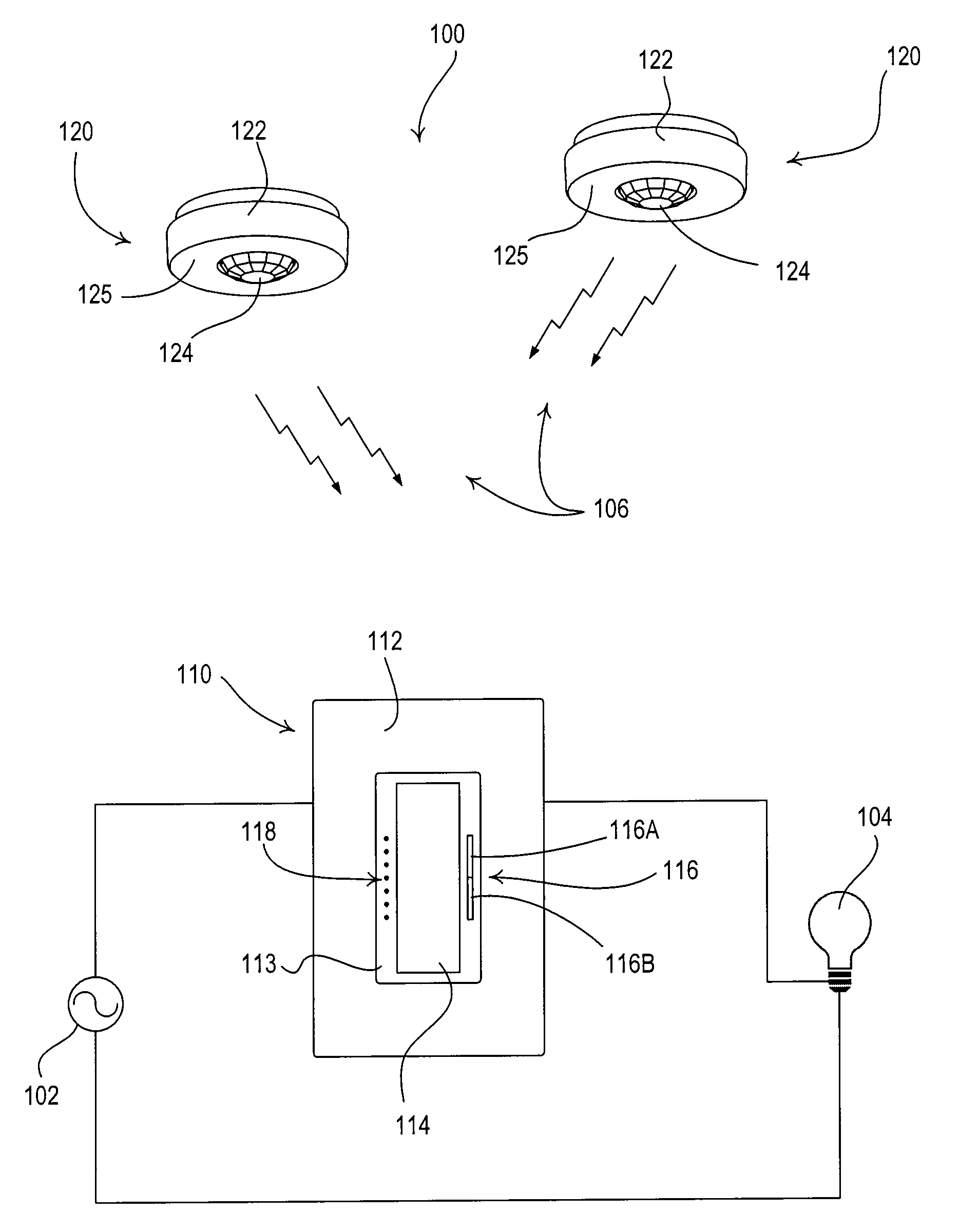
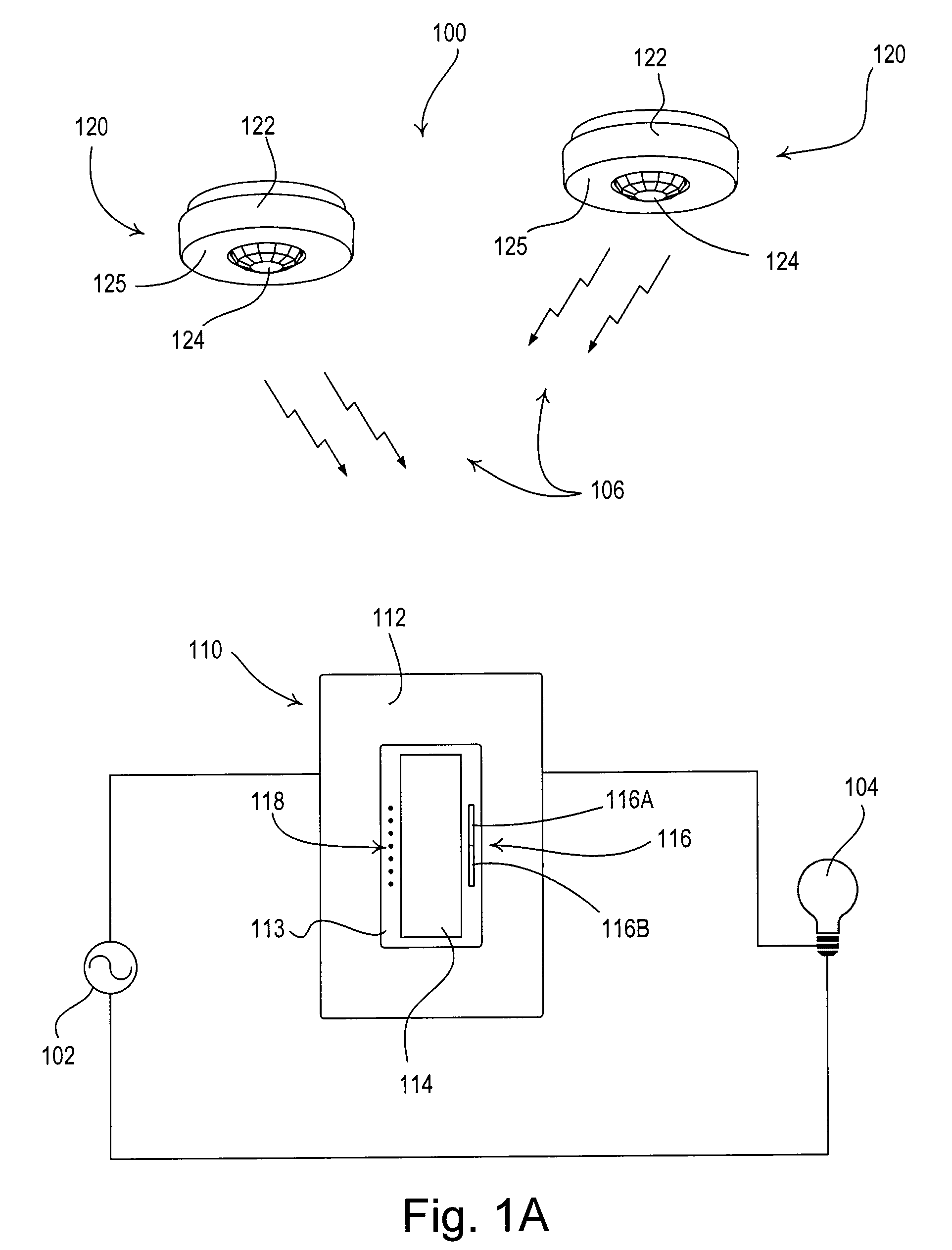
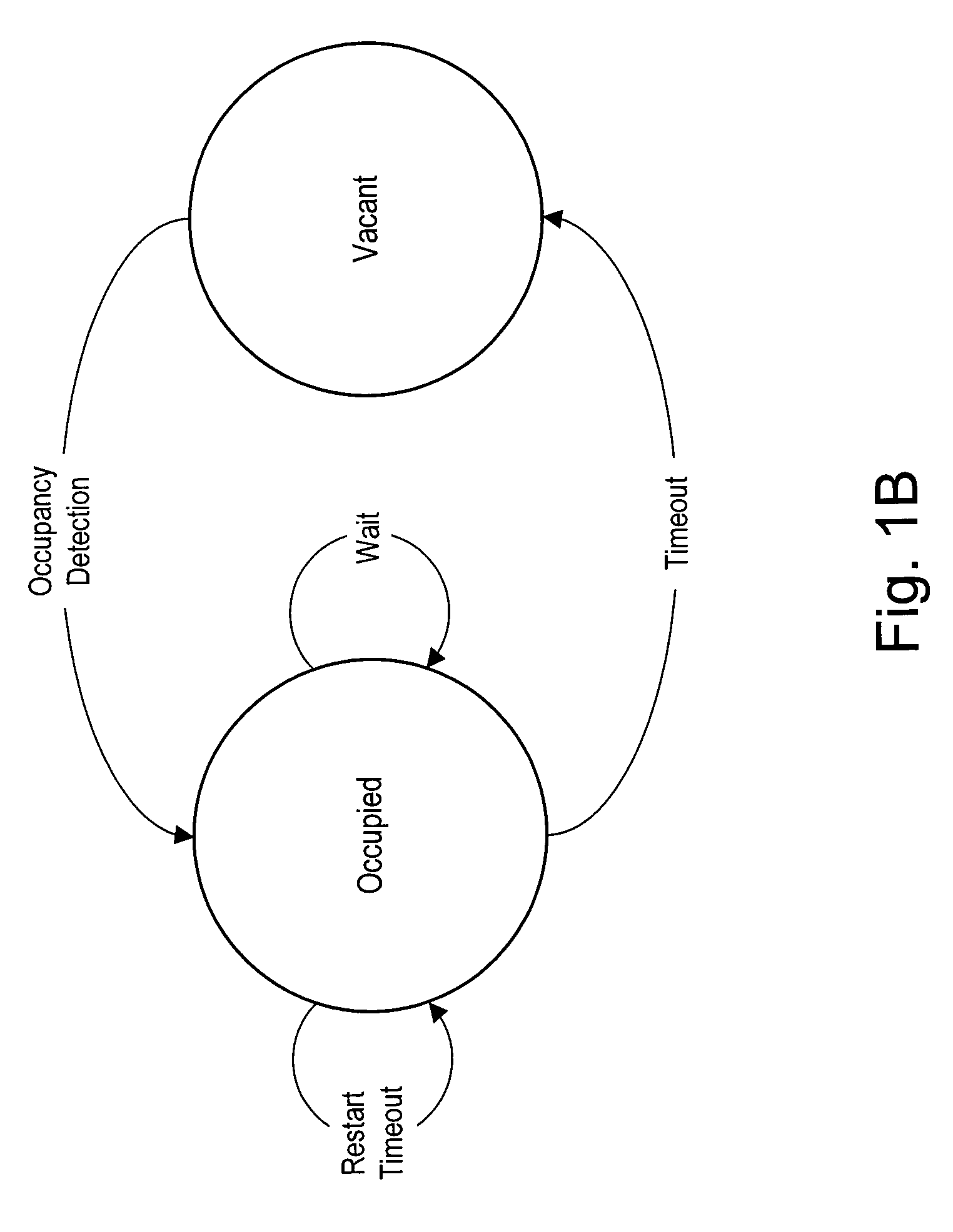
[0065]According to the present invention, the occupancy sensors 120 are each operable to store in a memory 240 the values of the various operating characteristics of the lighting control system 100, e.g., the occupancy voltage threshold, the ambient light level threshold, and the occupancy sensor timeout period TTIMEOUT. The memory 240 may be implemented as an external integrated circuit (IC) or as an internal circuit of the controller 230. To adjust the values of the operating characteristics, the user must access the occupancy sensor 120 to actuate the actuators 236. The occupancy sensors 120 use the operating characteristics to change between the occupied state and the vacant state as will be described in greater detail below. The occupancy sensors 120 also store the serial number in the memory 240. The serial number may be programmed into the memory 240, for example, during manufacture of the occupancy sensor 120.
[0066]The remote occupancy sensor 120 further comprises an RF tran...
second embodiment
[0100]According to the present invention, the dimmer switch 110 is operable to store in the memory 216 the values of the various operating characteristics of the lighting control system 100, e.g., the occupancy voltage threshold, the ambient light level threshold, and the occupancy sensor timeout period TTIMEOUT. The dimmer switch 110 may provide, for example, an advanced programming mode, such that the values of the operating characteristics may be adjusted in response to actuations of the toggle actuator 114 and the intensity adjustment actuator 116. An advanced programming mode is described in greater detail in U.S. Pat. No. 7,190,125, issued Mar. 13, 2007, entitled PROGRAMMABLE WALLBOX DIMMER, the entire disclosure of which is hereby incorporated by reference. Since the user does not need to access the occupancy sensors 120 (which may be mounted to a ceiling) to adjust the operating characteristics, the use of the toggle actuator 114 and the intensity adjustment actuator 116 of ...
third embodiment
[0110]FIG. 17A is a simplified block diagram of a lighting control system 100′ having a dimmer switch 110′ according to the present invention. The lighting control system 100′ may additionally comprise one or more remote controls 130. The remote control 130 comprises a plurality of actuators: an on button 132, an off button 134, a raise button 136, a lower button 138, and a preset button 140 (for recalling a preset lighting intensity stored in the memory 216 of the dimmer switch 110′). Alternatively, the remote control 130 could comprises a plurality of preset buttons. The remote control 130 transmits digital messages via the RF signals 106 to the dimmer switch 110′ in response to actuations of any of the actuators. The dimmer switch 110′ is responsive to digital messages containing the serial number of the remote control 130 to which the dimmer switch is associated. The dimmer switch 110′ is operable to turn on and to turn off the lighting load 104 in response to an actuation of th...
PUM
 Abstract
Description
Claims
Application Information
 - R&D
- Intellectual Property
- Life Sciences
- Materials
- Tech Scout
- Unparalleled Data Quality
- Higher Quality Content
- 60% Fewer Hallucinations
Browse by: Latest US Patents, China's latest patents, Technical Efficacy Thesaurus, Application Domain, Technology Topic, Popular Technical Reports.
© 2025 PatSnap. All rights reserved.Legal|Privacy policy|Modern Slavery Act Transparency Statement|Sitemap|About US| Contact US: help@patsnap.com


