
Light-emitting diodes using nano-rods and methods of manufacturing a light-emitting diode

a technology of light-emitting diodes and nano-rods, which is applied in the direction of nano-rods, semiconductor devices, electrical equipment, etc., can solve the problems of inefficient method of growing nano-rods, difficult to supply substantially uniform current to each of the nano-rods, and increase manufacturing costs, so as to achieve efficient growth

Active Publication Date: 2010-03-04
SAMSUNG ELECTRONICS CO LTD
View PDF34 Cites 41 Cited by
  • Summary
  • Abstract
  • Description
  • Claims
  • Application Information

AI Technical Summary

Benefits of technology

The patent text describes a light-emitting diode that includes nano-rods and methods of manufacturing it. The nano-rods have a structure that allows for efficient growth and uniform current supply. The diode also includes a supporting substrate, a reflection electrode, a transparent insulating layer, a transparent electrode, and an auxiliary electrode. The method involves growing the nano-rods on a growth substrate, removing the substrate, and forming a transparent electrode on the position where the substrate is removed. The technical effects of this patent include improved efficiency and uniform current supply to the nano-rods, as well as improved patterning of the auxiliary electrode.

Problems solved by technology

Also, the manufacturing costs increase due to the difficultly in growing the GaN compound semiconductor in a larger size area.
In the case of a LED that includes nano-rods, it is difficult to supply a substantially uniform current to each of the nano-rods.
Also, the method of growing the nano-rods may be inefficient.

Method used


Image

  • Light-emitting diodes using nano-rods and methods of manufacturing a light-emitting diode
  • Light-emitting diodes using nano-rods and methods of manufacturing a light-emitting diode
  • Light-emitting diodes using nano-rods and methods of manufacturing a light-emitting diode

Examples


Embodiment Construction

[0031]Various example embodiments will now be described more fully with reference to the accompanying drawings in which some example embodiments are shown. However, specific structural and functional details disclosed herein are merely representative for purposes of describing example embodiments. Thus, the invention may be embodied in many alternate forms and should not be construed as limited to only example embodiments set forth herein. Therefore, it should be understood that there is no intent to limit example embodiments to the particular forms disclosed, but on the contrary, example embodiments are to cover all modifications, equivalents, and alternatives falling within the scope of the invention.

[0032]In the drawings, the thicknesses of layers and regions may be exaggerated for clarity, and like numbers refer to like elements throughout the description of the figures.

[0033]Although the terms first, second, etc. may be used herein to describe various elements, these elements s...


PUM


Abstract

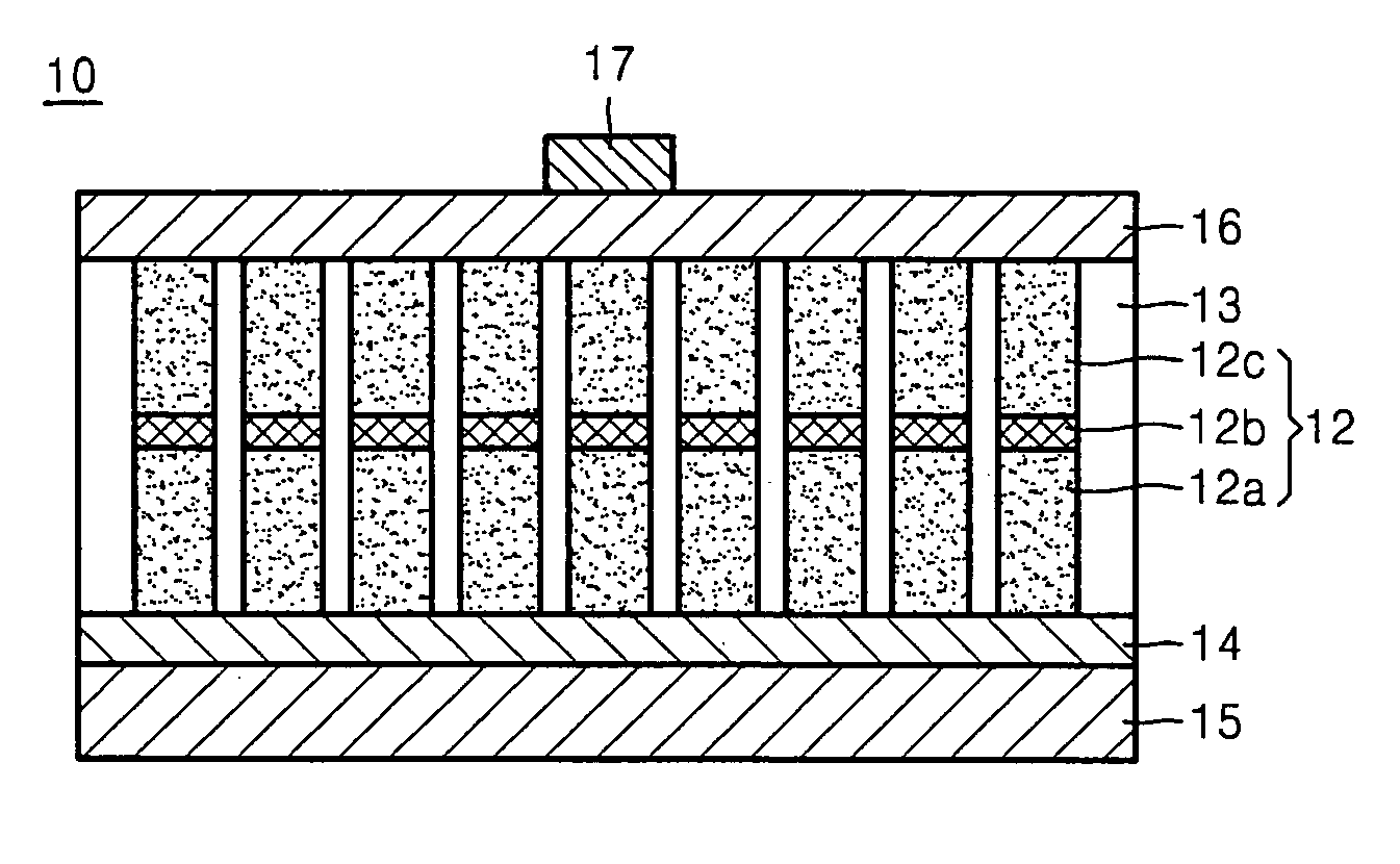
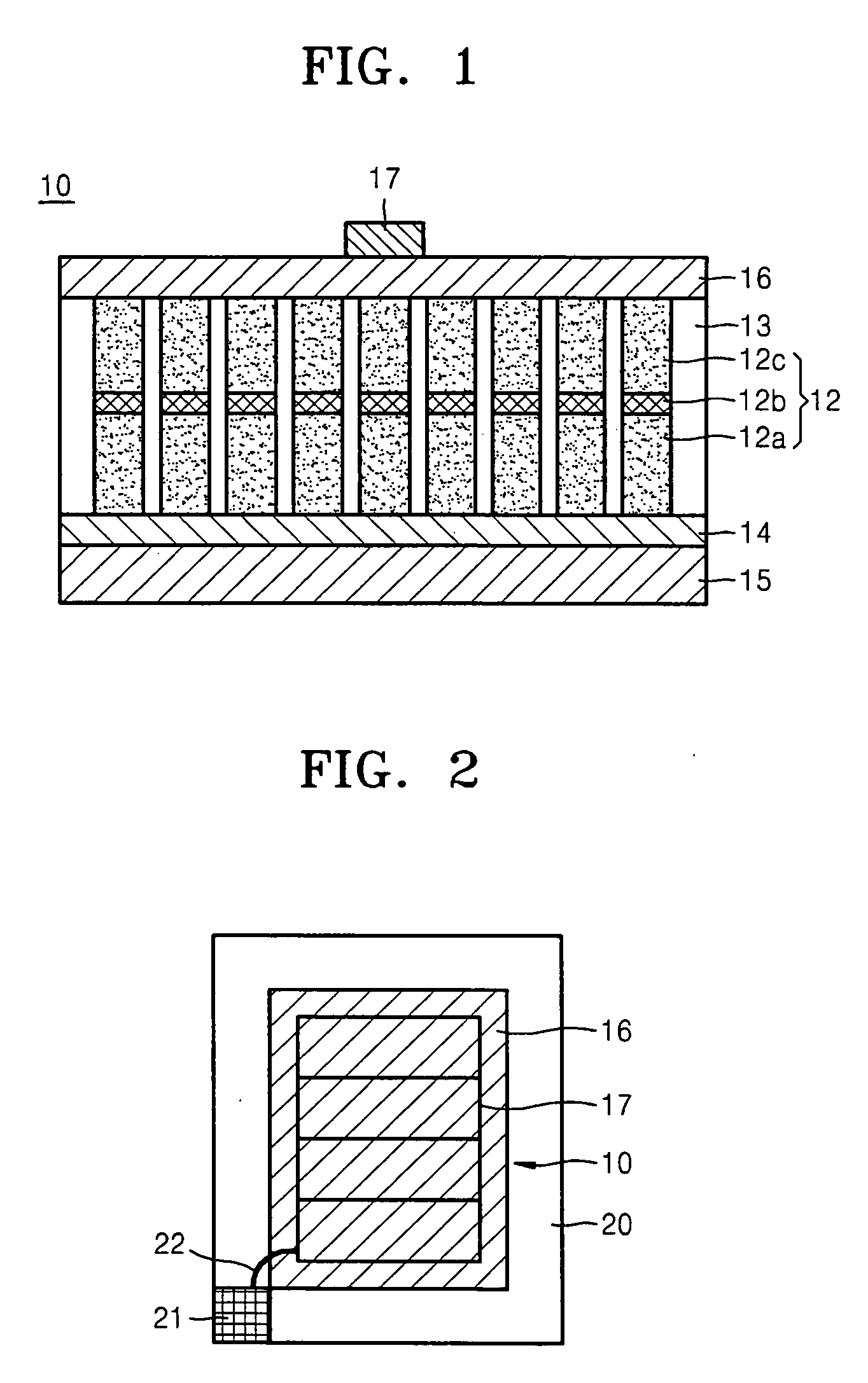
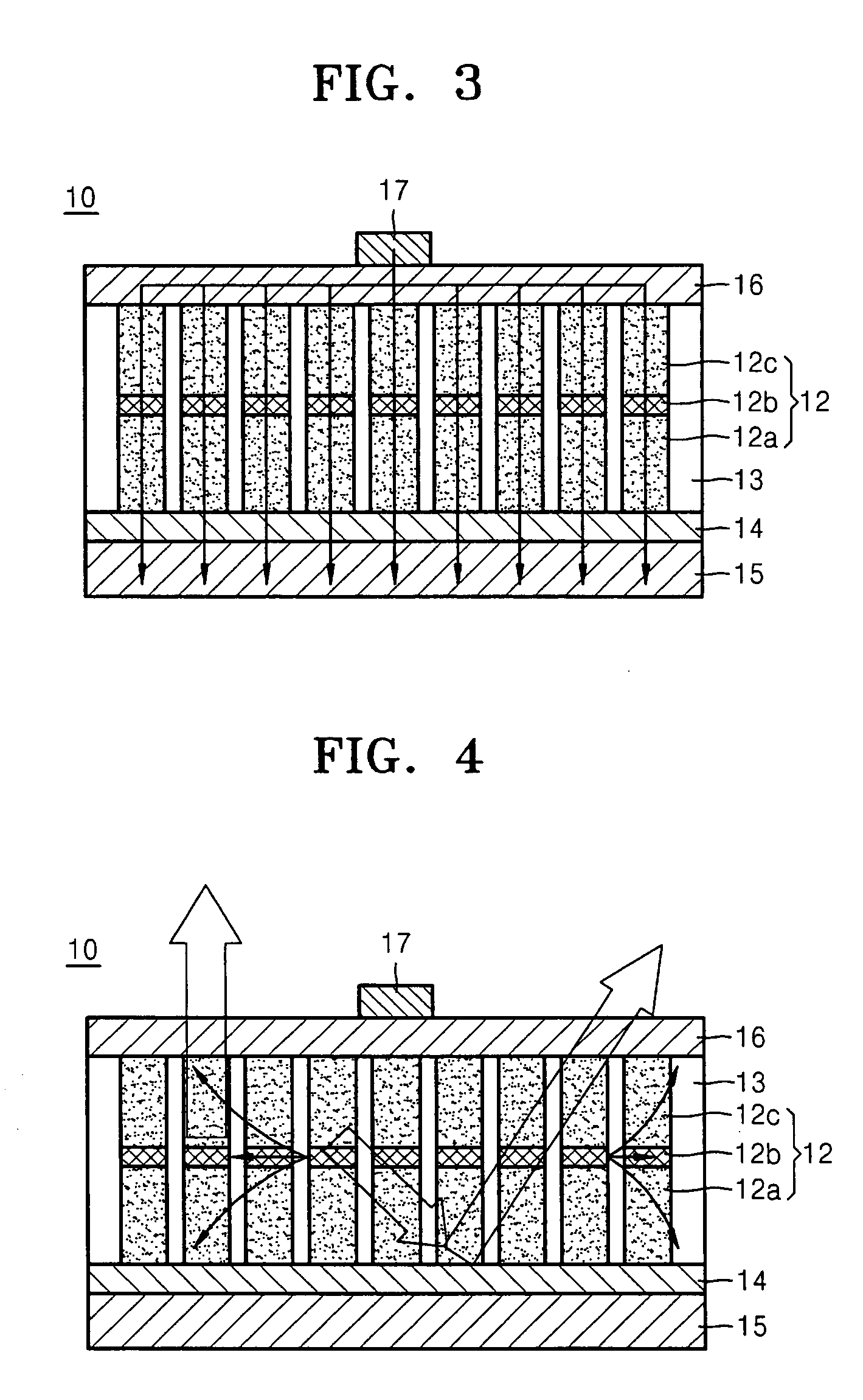
Light-emitting diodes, and methods of manufacturing the light-emitting diode, are provided wherein a plurality of nano-rods may be formed on a reflection electrode. The plurality of nano-rods extend perpendicularly from an upper surface of the reflection electrode. Each of the nano-rods includes a first region doped with a first type dopant, a second region doped with a second type dopant that is an opposite type to the first type dopant, and an active region between the first region and the second region. A transparent insulating layer may be formed between the plurality of nano-rods. A transparent electrode may be formed on the plurality of nano-rods and the transparent insulating layer.

Description

CROSS-REFERENCE TO RELATED APPLICATIONS[0001]This application claims the benefit of priority under 35 U.S.C. §119 from Korean Patent Application No. 10-2008-0087439, filed on Sep. 4, 2008, in the Korean Intellectual Property Office, the disclosure of which is incorporated herein in its entirety by reference.BACKGROUND[0002]1. Field[0003]Example embodiments relate to light-emitting diodes using nano-rods. Other example embodiments relate to methods of manufacturing a light emitting diode.[0004]2. Description of the Related Art[0005]A light-emitting diode (LED) that uses a semiconductor has high efficiency. A LED is also an environmentally friendly source of light. Light-emitting devices are widely used in various fields (e.g., displays, optical communications, automobiles, common illuminations, etc.).[0006]An LED technique for general illumination has been the focus of recent research due to the development of a white light LED technique. The white light LED may be produced using, fo...

Claims


Application Information

Patent Timeline
Patent Type & Authority Applications(United States)
IPC IPC(8): H01L33/00H01L21/00
CPCB82Y20/00H01L33/18H01L33/405Y10S977/722Y10S977/723Y10S977/721Y10S977/72Y10S977/932
Inventor MIN, BOKKIPARK, YOUNGSOOKIM, TAEKKIM, JUNYOUN
Owner SAMSUNG ELECTRONICS CO LTD
Learn More