
Ion source

a technology of ion source and ion source, which is applied in the field of ion source, can solve the problems of increasing the number of items correspondingly and complicated structure, and achieve the effect of simplifying the structure of ion source and reducing the number of items

Active Publication Date: 2010-03-04
NISSIN ION EQUIP CO LTD
View PDF21 Cites 39 Cited by
  • Summary
  • Abstract
  • Description
  • Claims
  • Application Information

AI Technical Summary

Benefits of technology

The present invention provides an ion source that generates an ion beam containing aluminum ions with a reduced number of items and a simplified structure. The ion source includes a plasma generating chamber, a hot cathode, an opposing reflecting electrode, and a magnet. The plasma generating chamber contains an ionization gas containing fluorine and a negative voltage is applied to the opposing reflecting electrode. The magnet generates a magnetic field along a line connecting the hot cathode and the opposing reflecting electrode. The aluminum particles are emitted into the plasma from the opposing reflecting electrode and the magnet. The backside reflecting electrode may also be used as the aluminum particle emitting electrode. The use of the magnet simplifies the process of generating the ion beam and increases the amount of aluminum ions in the ion beam. The ion source includes a backside reflecting electrode and a wall surface containing the opening portion of the plasma generating chamber, which may be formed of an aluminum containing material. The reduction of the number of items and simplification of the structure of the ion source make it easier to increase the amount of aluminum ions in the ion beam.

Problems solved by technology

Therefore, such a problem exists that the number of items is increased correspondingly and a structure becomes complicated.

Method used


Image

  • Ion source
  • Ion source
  • Ion source

Examples


Embodiment Construction

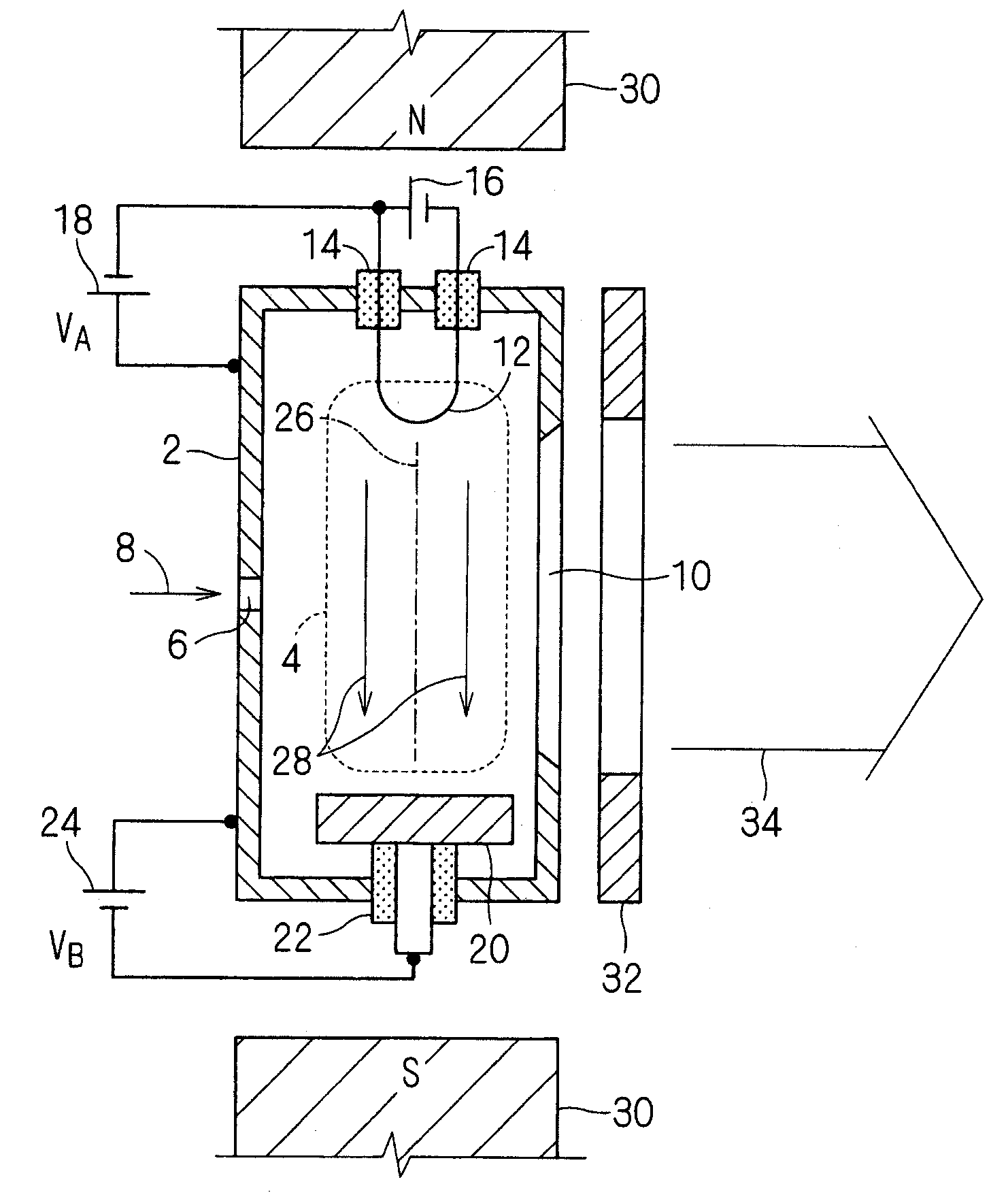
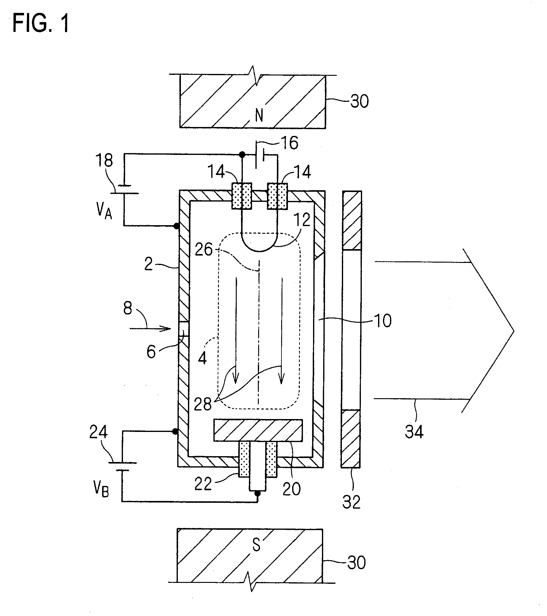
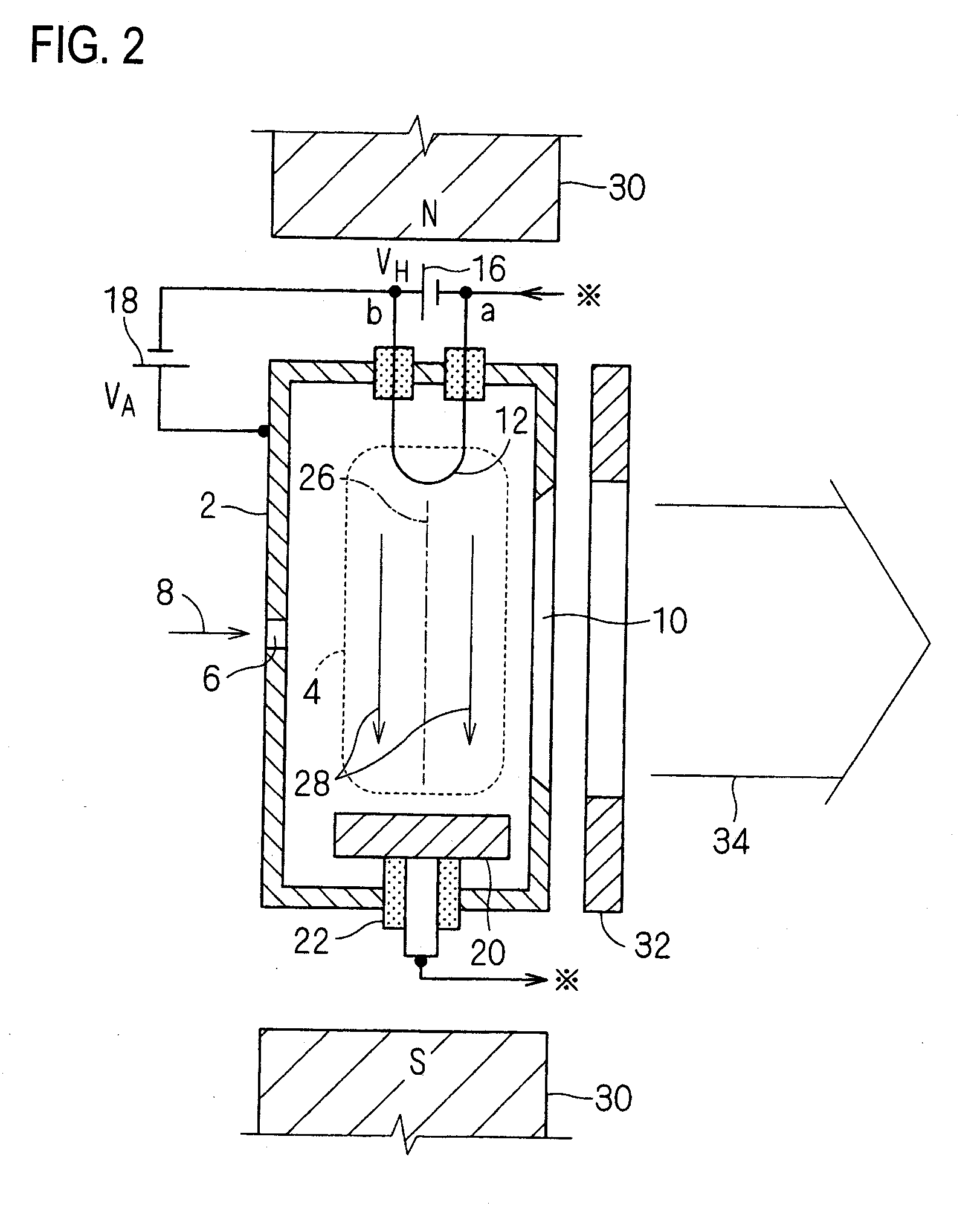
[0036]FIG. 1 is a schematic sectional view showing an embodiment of an ion source according to this invention. This ion source is the ion source that generates (extracts out) an ion beam 34 containing aluminum ions, and is equipped with a plasma generating chamber 2 that is used to generate a plasma 4 in an interior and also serves as an anode for an arc discharge. This plasma generating chamber 2 is shaped into a rectangular parallelepiped, for example, but the shape is not limited to this shape.

[0037]An ionization gas 8 containing fluorine is introduced into the plasma generating chamber 2 through a gas inlet port 6. The position of the gas inlet port 6 is not limited to a position in the illustrate example. The reason why the ionization gas 8 containing fluorine is used is that, since the fluorine has a very strong chemical action and has a strong reactivity with other materials, the plasma 4 generated by ionizing the ionization gas 8 containing fluorine has a strong action to em...


PUM


Abstract

An ion source includes a plasma generating chamber into which an ionization gas containing fluorine is introduced, a hot cathode provided on one side in the plasma generating chamber, an opposing reflecting electrode which is provided on other side in the plasma generating chamber and reflects electrons when a negative voltage is applied from a bias power supply to the opposing reflecting electrode, and a magnet for generating a magnetic field along a line, which connects the hot cathode and the opposing reflecting electrode, in the plasma generating chamber. The opposing reflecting electrode is formed of an aluminum containing material.

Description

TECHNICAL FIELD[0001]The present disclosure relates to an ion source which is employed in an ion implantation apparatus that implants aluminum ions into a target such as a silicon carbide (SiC) substrate, or the like, for example, and generates an ion beam containing the aluminum ions.RELATED ART[0002]An example of the ion source of this type is set forth in Patent Literature 1.[0003]In the related-art ion source set forth in Patent Literature 1, a plate formed of the aluminum containing material (e.g., aluminum oxide) is provided in the ionization chamber apart from an electrode (cathode) and a recoil plate as the components used for the plasma generation / confinement, and the plasma being generated by ionizing a fluoride gas (e.g., silicon tetrafluoride) is caused to erode the plate formed of the aluminum containing material such that the aluminum ions are emitted into the plasma.[Related Art Literature][Patent Literature][0004][Patent Literature 1] Japanese Patent No. 3325393 (par...

Claims


Application Information

Patent Timeline
Patent Type & Authority Applications(United States)
IPC IPC(8): H01J27/02
CPCH01J27/14
Inventor YAMASHITA, TAKATOSHIIKEJIRI, TADASHIIGO, TETSUYA
Owner NISSIN ION EQUIP CO LTD
Learn More