
System for supplying hydraulic fluid

a hydraulic fluid and system technology, applied in the direction of liquid handling, positive displacement liquid engines, liquid transferring devices, etc., can solve the problems of increased costs, unfavorable durability, and “dry” charge oil pumps, so as to reduce the negative pressure built up, prevent the flow of hydraulic fluid, and increase the viscosity of hydraulic fluid

Active Publication Date: 2010-03-04
DEERE & CO
View PDF7 Cites 4 Cited by
  • Summary
  • Abstract
  • Description
  • Claims
  • Application Information

AI Technical Summary

Benefits of technology

The present invention provides a system for supplying hydraulic fluid to a hydraulic system by using an operating reservoir and an auxiliary reservoir connected by a hydraulic line. An air pump is used to create a negative pressure in the auxiliary reservoir and to control the fluid level in the operating reservoir. The system allows for a constant supply of hydraulic fluid to the hydraulic system and ensures that the fluid level in the operating reservoir is always covered by hydraulic fluid. The system is cost-effective and can be easily integrated into existing hydraulic systems.

Problems solved by technology

These lead to additional costs due to the associated increased costs of the configuration.
If, for example, increased hydraulic fluid consumption occurs during operation of the vehicle units, there is the possibility, that the operating reservoir is completely emptied into the auxiliary reservoir due to the continued operation of the charge oil pump, so that the charge oil pump runs “dry”, or is un-lubricated during its continued operation.
The latter condition may not only be detrimental to the durability of the charge oil pump, but in addition leads to an interruption of the lubrication of the differential gear in the differential housing.

Method used


Image

  • System for supplying hydraulic fluid
  • System for supplying hydraulic fluid
  • System for supplying hydraulic fluid

Examples


first embodiment

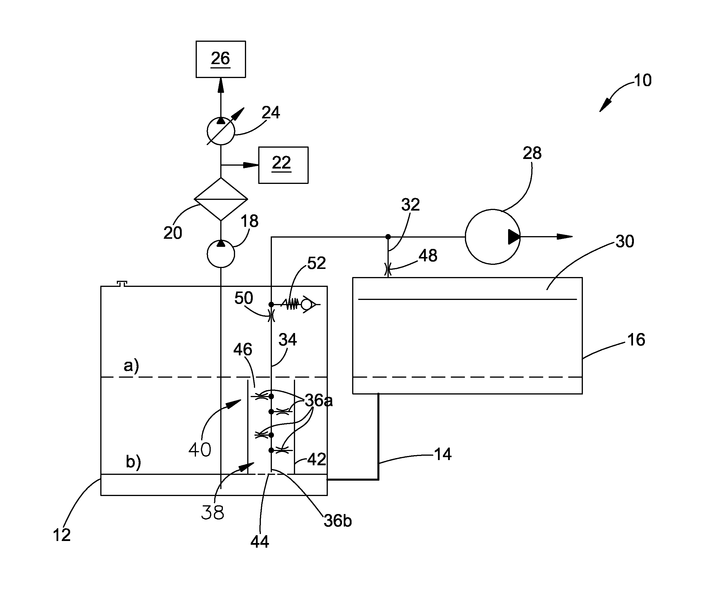
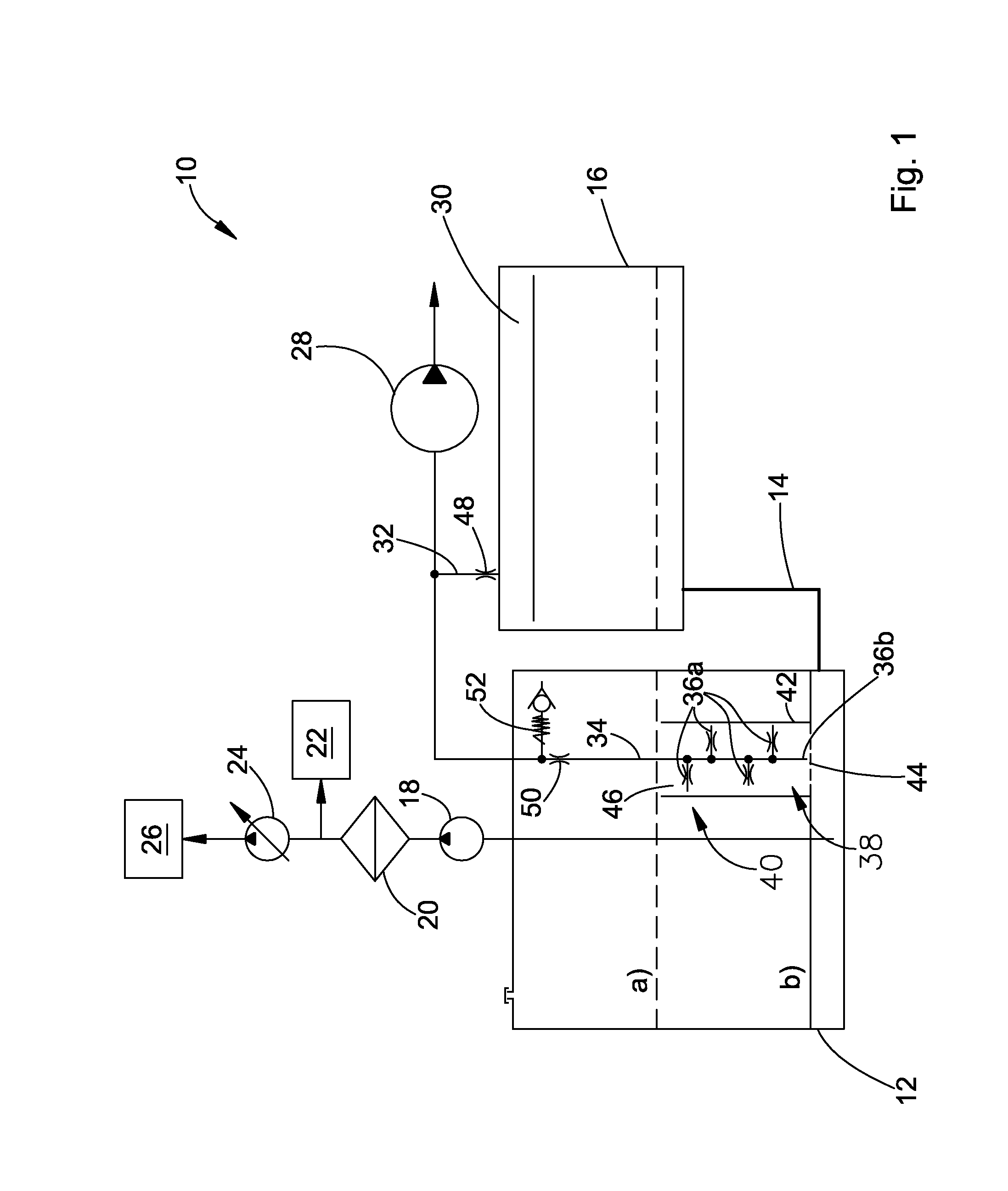
[0024]FIG. 1 shows a system 10 for supplying hydraulic fluid to a hydraulic system 26 in an agricultural utility vehicle (not shown). The vehicle may be a tractor, a harvesting machine, a forage harvester or a sprayer.

[0025]This system 10 may be located in an engine room or in the area of a gear box system of the vehicle. The system 10 includes an operating reservoir 12 that holds hydraulic fluid used in the operation of the hydraulic system, and an auxiliary reservoir 16 for the temporary storage or buffering of hydraulic fluid withdrawn from the operating reservoir 12. Auxiliary reservoir 16 is connected to the operating reservoir 12 by a hydraulic line 14.

[0026]The operating reservoir 12 may be formed by a differential gearbox housing of a gearbox included in the differential housing of the vehicle. The hydraulic fluid located in the differential housing simultaneously forms a sump for the lubrication of the differential gearbox. The hydraulic fluid in this case is conventional h...

third embodiment

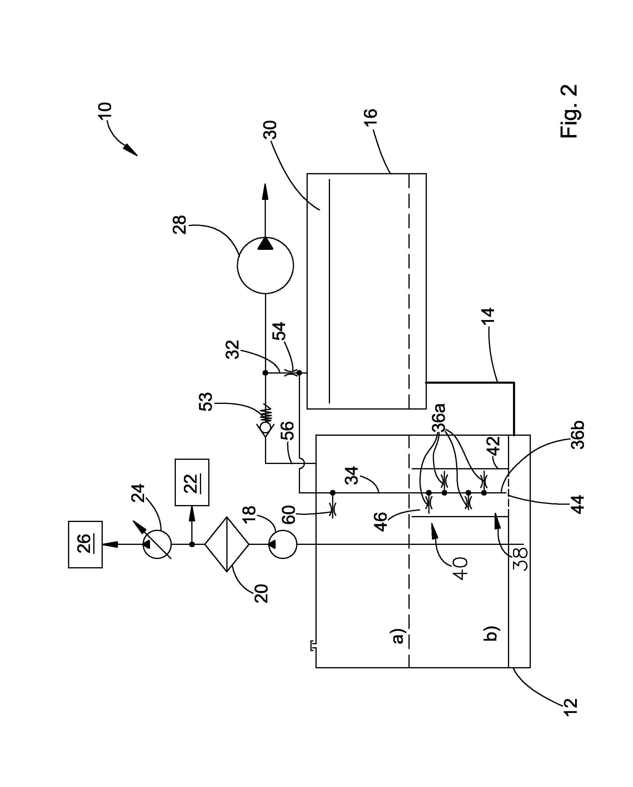
[0038]FIG. 3 shows the system which differs from the system of FIG. 2 in such a way that a reverse flow check valve 58 is provided in place of the throttle 54, which is arranged so that it is blocked in case of an intrusion of hydraulic fluid. The reverse flow check valve 58 is provided with a floating ball valve that is forced against a valve seat in case of an intrusion of hydraulic fluid in such a way that an undesired through flow of hydraulic fluid is prevented.

[0039]In contrast to both of the above embodiments, the suction line 32 does not end directly in the control line 34. Rather, there is merely an indirect connection between the suction line 32 and the control line 34. For this purpose the control line 32 also ends in the fluid-free portion 30 of the auxiliary reservoir 16. Since the two lines 32 and 34 indirectly communicate with each other in this case an additional protection is provided against an undesired intrusion of hydraulic fluid drawn from the operating reservo...


PUM


Abstract

The invention concerns a system for supplying hydraulic fluid to a hydraulic system, with an operating reservoir that accepts the hydraulic fluid provided for the operation of the hydraulic system and an auxiliary reservoir connected to the operating reservoir over a hydraulic line for intermediate storage of hydraulic fluid withdrawn from the operating reservoir. According to the invention, an air pump is available that is connected on the one hand on its low pressure side to a suction line that ends in a fluid free area of the auxiliary reservoir, so that a negative pressure can be built up in the auxiliary reservoir as against the external atmospheric pressure, and that is connected, on the other hand, to a control line that is provided with a control opening that is covered by the hydraulic fluid in the operating reservoir at least before the air pump is put into operation.

Description

FIELD OF THE INVENTION [0001]This application claims priority based on German Application No. 10 2008 041 799.8, filed on Sep. 3, 2008 (Abandoned), and German Application No. 10 2008 043 449.3, filed on Nov. 4, 2008, which is hereby incorporated by reference in to this application. The present invention relates to a supply system for supplying hydraulic fluid to a hydraulic system.BACKGROUND OF THE INVENTION [0002]John Deere Tractors of the Series 6030 and 7030 use a system in which a charge oil pump continuously conveys hydraulic fluid against the force of gravity from an operating reservoir formed in the differential housing into an auxiliary reservoir located at a higher level, where the hydraulic fluid is charged starting from the auxiliary reservoir over a controllable high pressure pump into a hydraulic system for the operation of vehicle hydraulic units. Hydraulic fluid no longer required by vehicle units is conducted back into the operating reservoir. The vehicle hydraulic u...

Claims


Application Information

Patent Timeline
Patent Type & Authority Applications(United States)
IPC IPC(8): F15D1/00
CPCF15B1/26F15B2211/615F15B2211/20592Y10T137/86187Y10T137/85978Y10T137/86043Y10T137/3109Y10T137/86348
Inventor WIENS, SCOTT R.SCHAEFER, HELMUTBRUESER, CHRISTIANLANGE, HARM-HENDRIK
Owner DEERE & CO
Learn More