
Solar panel support module and method of creating array of interchangeable and substitutable solar panel support modules

a solar panel and support module technology, applied in the direction of machine supports, heat collector mounting/supports, light and heating equipment, etc., can solve the problems of inability to independently monitor the solar panel structure, the solar panel structure cannot be uniformly and evenly seated on an undulating or variable surfaced roof, and the string inverter cannot provide monitoring at the solar panel level. , to achieve the effect of less labor, less time to construct the rooftop array, and cost saving

Active Publication Date: 2010-02-25
SOCORE ENERGY
View PDF57 Cites 104 Cited by
  • Summary
  • Abstract
  • Description
  • Claims
  • Application Information

AI Technical Summary

Benefits of technology

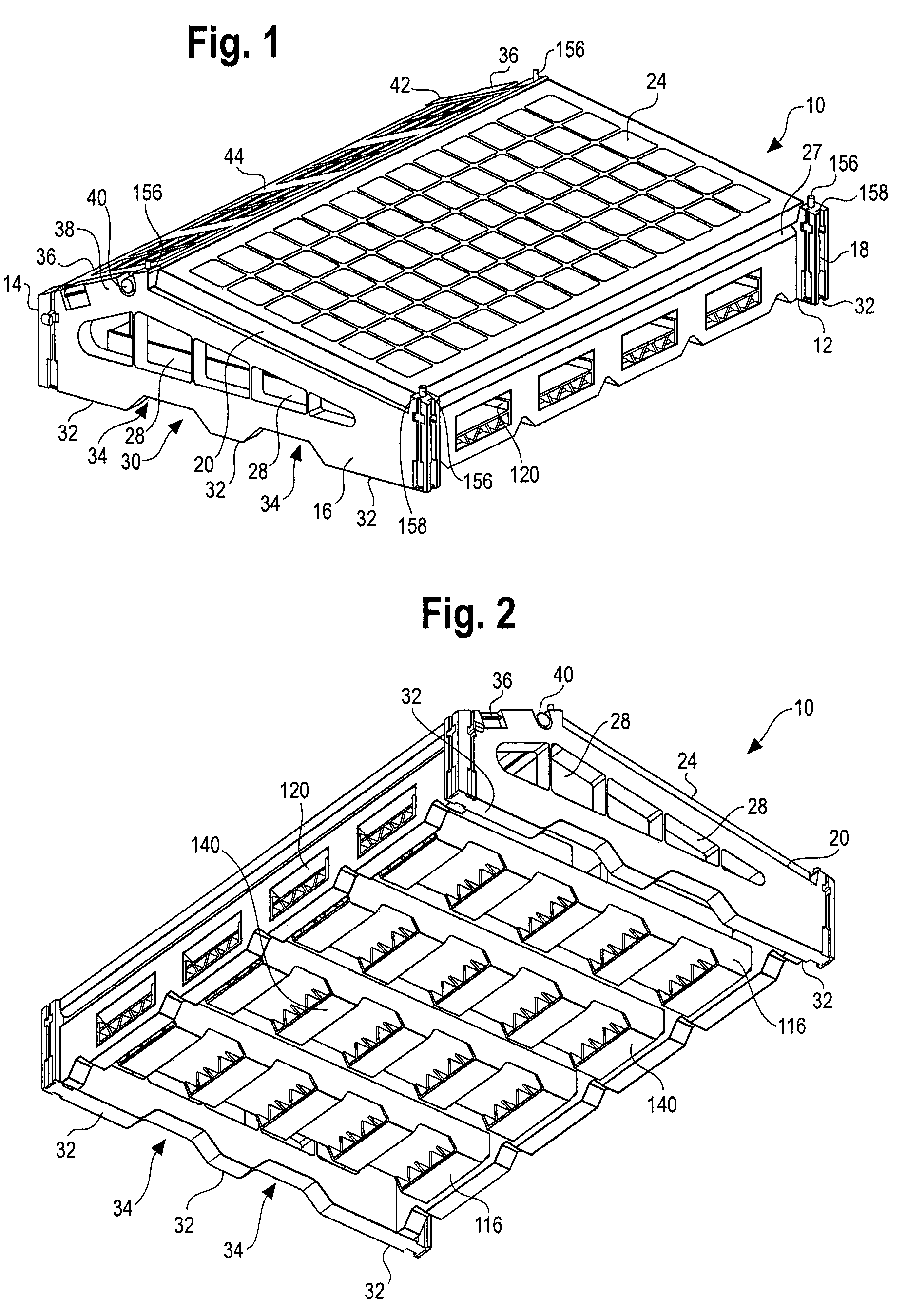
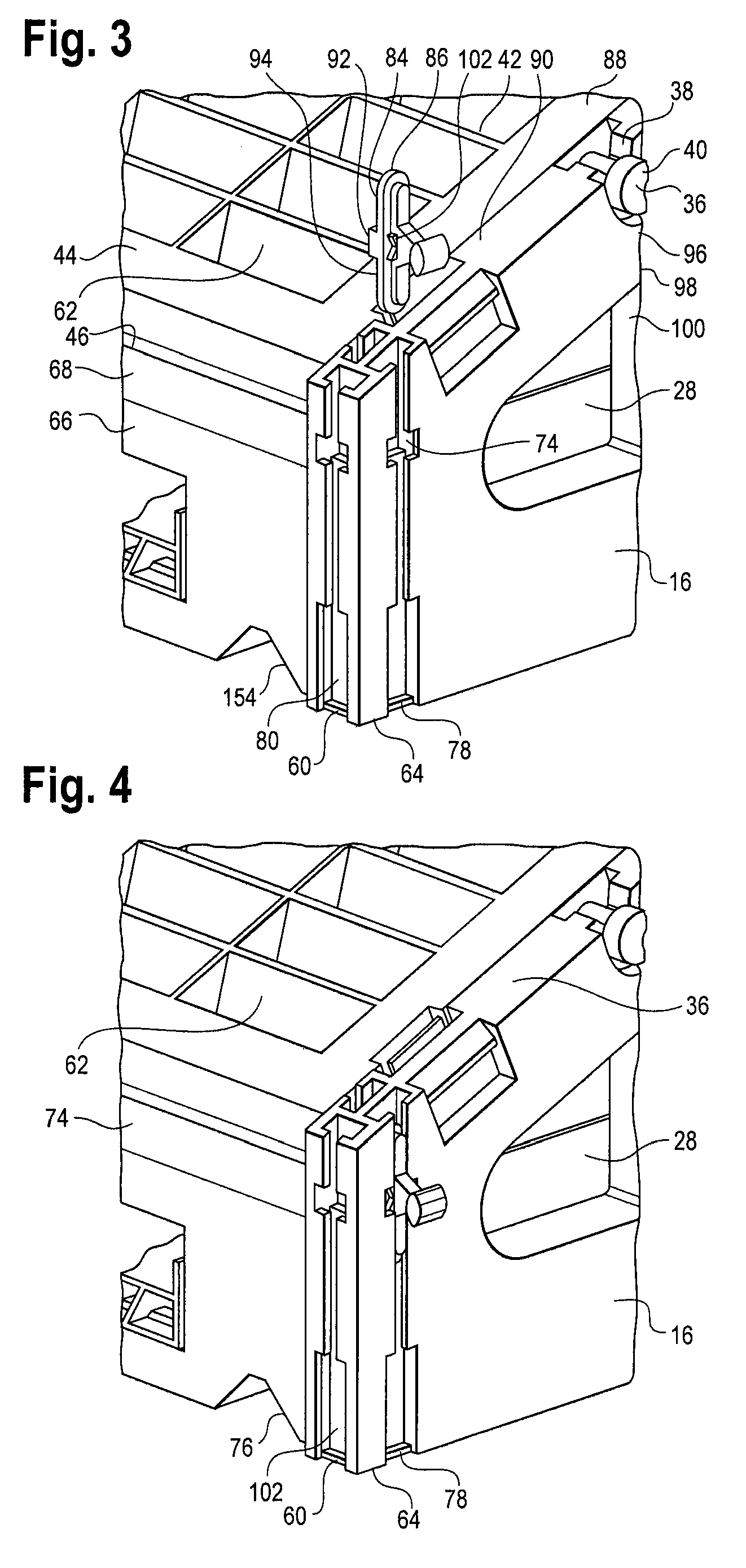
[0006]The present invention is an apparatus and method of providing a solar energy electrical generation system comprising an array of removably interengable PV solar panel support modules. The support modules are each uniformly constructed and are configured to be interengaged both front to back and side to side by a male-female pivot connection to create a system formed into an array of solar panel support modules that are removably and flexibly attached to each other, whereby one or more modular units can be removed from a first array and readily substituted into the same array or into a second array. Each support module is flexibly and removably connected to an adjacent module by a unique pivot connection to accommodate placement of the modules on a rooftop having a variable or undulating surface. In the illustrated embodiment, each support module includes an individual micro-inverter adapted to be electrically interconnected to the solar panel supported by the module, and also to be connected via quick connect / quick disconnect assemblies to the micro-inverters mounted on adjacent solar panel modules forming the array. This allows each solar panel to be monitored individually, and allows each support module and its associated solar panel to be moved to and substituted into a second array, and re-installed in the original array. Also, a complete solar panel array is built unit-by-unit, by connecting together the desired number of support modules that each mount a solar panel and a micro-inverter. The present invention also contemplates the use of integral solar panels and micro-inverters, as available.
[0008]A need also exists for solar panel support modules designed to stack one on top of the other for ease of shipment to or from an installation site. A need also exists for a solar panel support module to be preassembled with the solar panel, micro-inverter and wiring in place on the module prior to delivering the assembled module to the installation site. At the installation site, the pre-assembled modules of the present invention are mechanically interengaged and electrically connected to each other. This requires less labor and less time to construct the rooftop array, thus providing cost savings.

Problems solved by technology

Since rooftops generally are not always flat, and may have a variable or undulating surface, it is difficult to uniformly and evenly seat such permanent or semi permanent support structures on an undulating or variable surfaced roof.
These solar panel structures cannot be independently monitored.
However, string inverters do not provide monitoring at the solar panel level, have a relatively short life span, and are not available in a modular construction.
Also, present solar panel support structures that are permanently or semi-permanently interconnected are not readily movable as individual units to a different location, such as when a roof must be replaced, end of a contract term, or the like.
Also, current solar panel systems cannot be easily reconfigured into a new system, such as reconfiguring a 100 kW array as two 50 kW arrays, or two 100 kW arrays could become one 200 kW array.

Method used


Image

  • Solar panel support module and method of creating array of interchangeable and substitutable solar panel support modules
  • Solar panel support module and method of creating array of interchangeable and substitutable solar panel support modules
  • Solar panel support module and method of creating array of interchangeable and substitutable solar panel support modules

Examples


Embodiment Construction

[0028]Referring to FIG. 1, the solar panel support module of the present invention is generally designated by the numeral 10, and comprises a front panel 12, a rear panel 14, and side panels 16, 18, each made of plastic or other suitable material. Each of the side panels 16, 18 has a slanted, substantially flat upper surface 20, 22 (FIG. 9) upon which PV solar panel 24 is placed. Solar panel 24 is attached on its long edges to the upper surface 27 of front panel 12 and to a beam 29 (FIG. 9) extending from side panel 16 to side panel 18, such as by screw s 26 (FIG. 15), or other suitable fasteners or integral mounting structures as are known in the art. Solar panel 24 is also supported on its long edges by the upper surface 27 of front panel 12 and to a beam 29 (FIG. 9) extending from side panel 16 to side panel 18. As seen in FIG. 1, solar panel 24 slants downward towards front panel 12 at an angle of five degrees or more. Each side panel 16, 18 also includes a plurality of aperture...


PUM


Abstract

A solar panel array support system including a plurality of removable, interengaged adjacent support modules of similar configuration. Each support module mounts a PV solar panel, and also a DC-AC inverter electrically connected to the solar panel. The DC-AC inverter is also electrically connectable to additional DC-AC inverters mounted to the adjacent solar panel support modules. Each support module includes flexible male connector elements that enter a slot forming a female connector element in an adjacent support module to pivotally and removably engage each support module to another. Individual modules or a plurality of solar panel support modules can be readily removed from and replaced in a solar panel array, and can be readily removed and installed to form a second modular solar panel array.

Description

[0001]The present invention relates to solar panel support modules and a method of interengaging a plurality of similarly constructed modules to form an array of solar panels extending over a surface, such as the roof of a building. Each module is removable from a given array, and can be added to or substituted when necessary in the same array or another solar panel array at a different location. Each module includes a PV solar panel and a micro-inverter electrically connected to the module-supported solar panel and to adjacent solar panels in the array.BACKGROUND OF THE INVENTION[0002]Photovoltaic (PV) solar panels that generate electrical power from the sun's energy are known. In commercial and residential environments, these panels are mounted on a support made usually of iron or extruded aluminum, and are typically arranged over the roof of a building, such as an office building, shopping mall or residential structure, and either attached directly to the roof or are ballasted or...

Claims


Application Information

Patent Timeline
IPC IPC(8): F24J2/46
CPCF24J2/5237F24J2/5239F24J2/526F24J2002/5279H02S20/24Y02E10/47Y02B10/14Y02B10/12H02S40/32Y02B10/20F24S2025/013F24S25/16F24S25/11F24S25/65F24S2025/6007Y02E10/50Y02B10/10
Inventor JONES, JEREMYROY, J.S.
Owner SOCORE ENERGY
Learn More