
Working Vehicle with HST

Active Publication Date: 2010-02-25
YANMAR POWER TECHNOLOGY CO LTD
View PDF4 Cites 9 Cited by
  • Summary
  • Abstract
  • Description
  • Claims
  • Application Information

AI Technical Summary

Benefits of technology

[0015]With regard to a working vehicle with an HST according to the present invention, which has an HST having a hydraulic pump and a hydraulic motor, comprising: a main clutch disposed between the HST and an engine; a power transmission means disposed between the HST and a wheel; an actuator changing slant angle of a movable swash plate of the hydraulic pump of the HST; and a control means controlling actuation of the actuator, a main clutch connection / disconnection detection means detecting connection status of the main clutch and a vehicle speed detection means detecting vehicle speed are provided, each of the detection means is connected to the control means, when the vehicle speed is not less than the set speed at the time of disconnecting the main clutch, the slant angle of the movable swash plate of the hydraulic pump is held at the angle at which the main clutch is disconnected.
[0016]Accordingly, when the main clutch is disconnected at the time of running for the reduction or the like, the overspeed of the hydraulic pump, an input shaft thereof or a clutch disc of the main clutch is prevented. Then, these members or members near them is prevented from being damaged so that the safety is secured and the durability of the HST is improved. Even if the main clutch is switched from the disconnection state to the connection state, the movable swash plate of the hydraulic pump is not at the neutral position, whereby the sudden braking is prevented.
[0017]With regard to the working vehicle with the HST according to the present invention, when the vehicle speed is less than set speed while the main clutch is disconnected, the movable swash plate of the hydraulic pump is rotated to the neutral position. Accordingly, when the vehicle speed is not more than set speed, the movable swash plate of the hydraulic pump can be returned to the neutral position without causing the overspeed of the movable swash plate of the hydraulic pump, the pump input shaft, and furthermore the clutch disc of the main clutch. Therefore, the sudden start at the time of connecting the main clutch is prevented.
[0018]With regard to the working vehicle with the HST according to the present invention, when the vehicle speed detection means does not detect the vehicle speed, the slant angle of the movable swash plate of the hydraulic pump is controlled so that the vehicle speed is smaller than the set speed. Accordingly, the vehicle speed is limited smaller than the set speed. Even if the vehicle speed is not detected because of the obstacle of the vehicle speed detection means or the like, the overspeed of the hydraulic pump, the pump input shaft thereof, and furthermore the clutch disc of the main clutch is prevented certainly. Moreover, even if the vehicle is stopped compulsorily in the field, a footing for an operator can be secured and moving work such as tillage can be continued.
[0019]With regard to the working vehicle with the HST according to the present invention, a sub transmission is provided in the power transmission means, and in the case that the vehicle speed detection means does not detect vehicle speed, when the sub transmission is at the low speed position, slant angle of the movable swash plate of the hydraulic pump can be changed suitably. Accordingly, the running at the vehicle speed lower than the set speed can be performed while the speed change is performed with the HST, whereby the running or work can be continued.
[0020]With regard to the working vehicle with the HST according to the present invention, the vehicle speed detection means comprises a rotation detection means, which outputs a pulse signal corresponding to rotation of a drive shaft of the wheel, and a conversion means, which outputs voltage corresponding to frequency of the pulse signal of the rotation detection means. Accordingly, compared with the case that the vehicle speed detection means only has the rotation detection means, the obstacle or extraordinariness of the vehicle speed detection means can be detected easily.

Problems solved by technology

However, at the time of high speed running, when the main clutch is disconnected and the movable swash plate of the hydraulic pump is rotated and slanted so that the slant angle thereof is small near the neutral position, the rotational driving force from a wheel is transmitted to the hydraulic motor, and the hydraulic motor is actuated as a pump and the hydraulic pump is actuated as a motor, whereby the overspeed of the hydraulic pump, an input shaft thereof or a clutch disc of the main clutch may occur so as to damage these members or members near them.
Furthermore, when the vehicle speed cannot be detected because of obstacle of a vehicle speed detection means or the like, whether the vehicle speed is high or not cannot be judged.
However, when the vehicle is stopped compulsorily on the field, a footing for an operator cannot be secured and moving work such as tillage cannot be continued, whereby it is not convenient for the operator.

Method used


Image

  • Working Vehicle with HST
  • Working Vehicle with HST
  • Working Vehicle with HST

Examples


Embodiment Construction

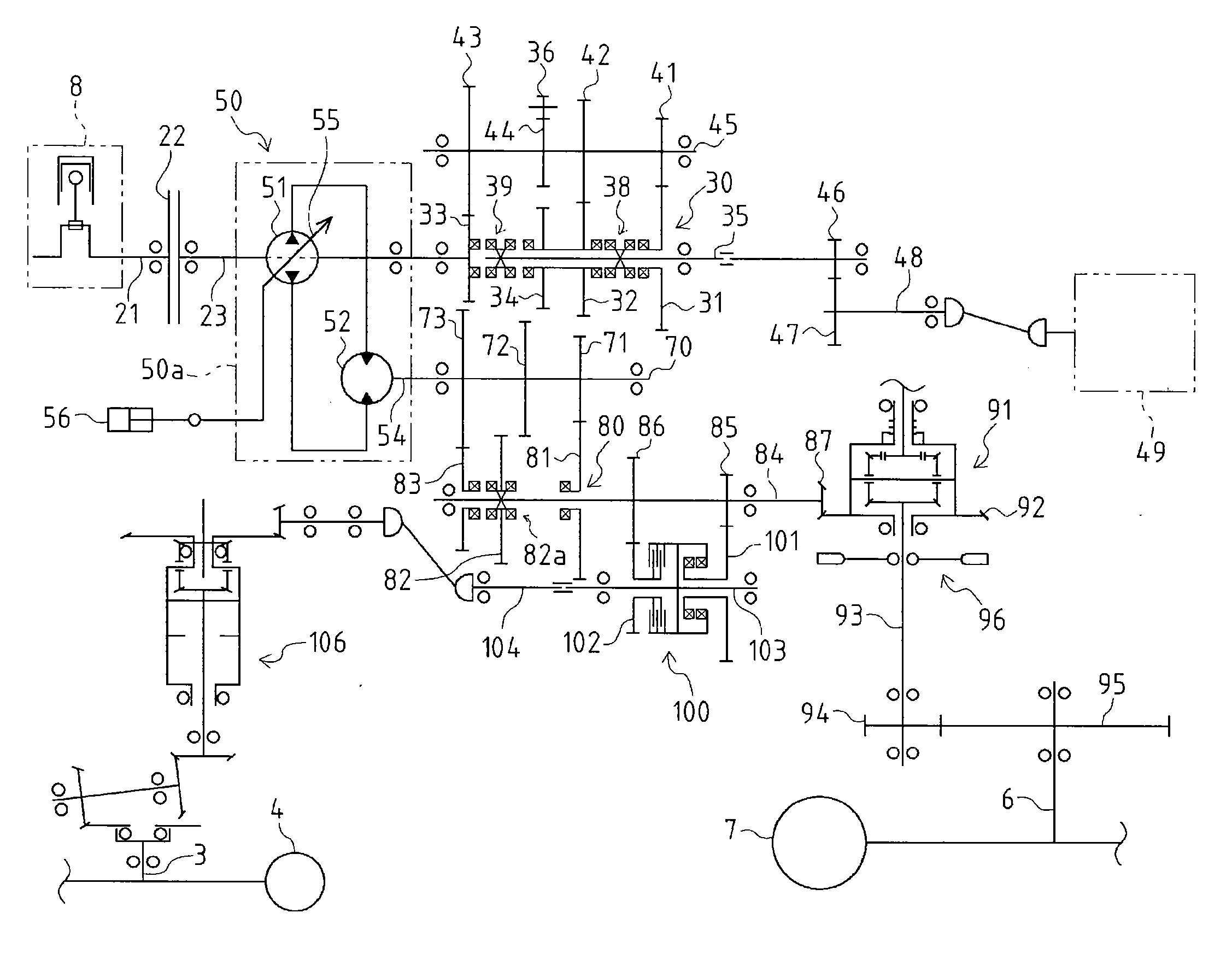
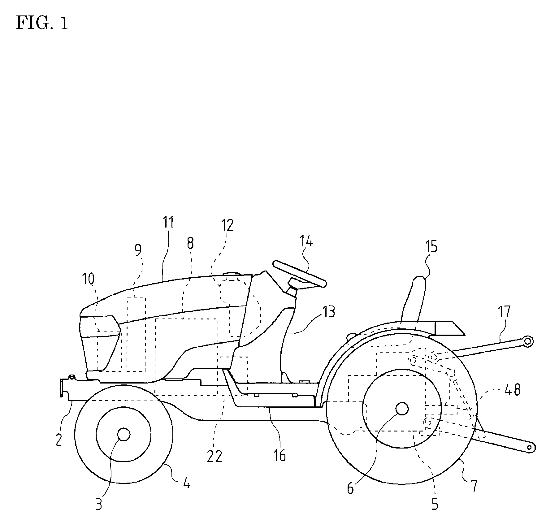
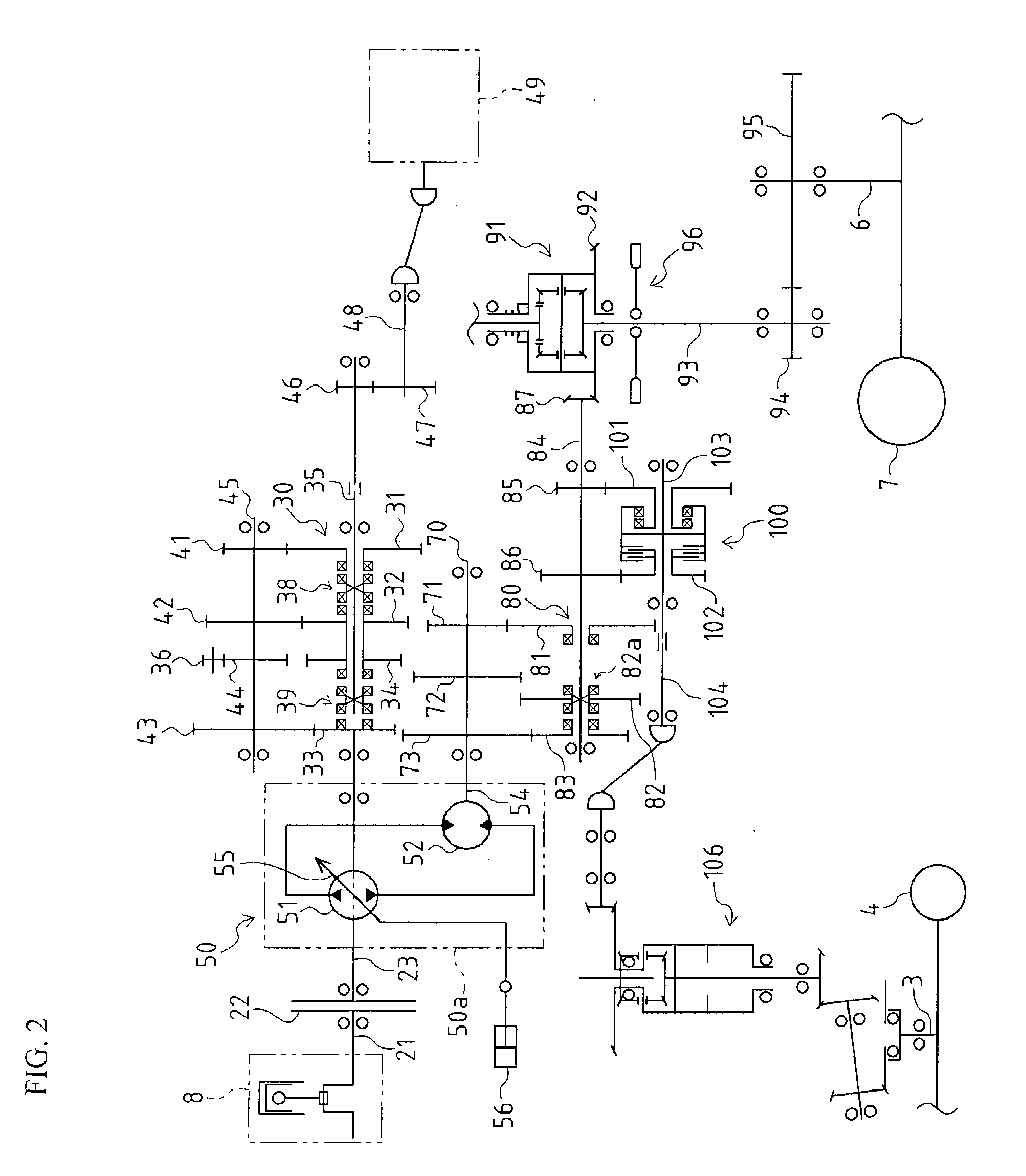
[0051]Explanation will be given on schematic construction of a tractor as a working vehicle with an HST (hydraulic stepless transmission) according to an embodiment of the present invention.

[0052]With regard to the working vehicle, as shown in FIG. 1, a front axle casing is rockably disposed in a lower front portion of a body frame 2, and front wheels 4 are attached to left and right ends of a front axle 3 pivotally supported by the front axle casing. A transmission 5 is fixed to a rear portion of the body frame 2. Rear axle casings are respectively disposed on left and right side surfaces of a rear portion of the transmission 5. A rear wheel 7 is attached to an end of a rear axle 6 pivotally supported by each of the rear axle casings.

[0053]An engine 8 is mounted on a longitudinal middle portion of the body frame 2. A radiator 9 and a battery 10 are arranged before the engine 8 and a fuel tank 12 is arranged behind the engine 8. The engine 8, the radiator 9, the battery 10 and the f...


PUM


Abstract

A working vehicle with an HST in which over-rotation of a hydraulic pump in the HST or the pump input shaft thereof is prevented when a main clutch is disconnected during a run. When a main clutch connection / disconnection detection means (112) detects (S2) the disconnection state of the main clutch (22) during a run, a control means (110) judges (S3) whether a vehicle speed detected by a vehicle speed detection means (116) is at least a set speed or not, and if the vehicle speed is at least the set speed, the movable swash plate (55) of the hydraulic pump (51) in an HST (50) is controlled to sustain it at the current inclination angle (S4).

Description

TECHNICAL FIELD[0001]The present invention relates to a working vehicle with an HST, that is, hydraulic stepless transmission. In more detail, the present invention relates to control of a movable swash plate of a hydraulic pump of the HST when a main clutch is disconnected at the time of running.BACKGROUND ART[0002]Conventionally, with regard to an HST having a hydraulic pump and a hydraulic motor, there is well known an art that a movable swash plate of the hydraulic pump or the hydraulic motor of variable capacity type is rotatively controlled by a hydraulic servo mechanism so as to adjust the capacity of the hydraulic pump or the hydraulic motor. As the hydraulic servo mechanism, there is known an automotive mechanism that the movable swash plate is rotated automatically in proportion to the increase of rotation speed of the hydraulic pump by an electromagnetic valve attached to the hydraulic pump or the body of the HST, and a manual servo mechanism that the movable swash plate ...

Claims


Application Information

Patent Timeline
IPC IPC(8): F16H61/38F16H39/00B60W30/18
CPCB60K17/10B60W10/02B60W10/103B60W30/18072F16H61/47B60W2510/0208B60W2520/10B60Y2200/221F16H61/431B60W50/029
Inventor NOMURA, HITOSHIHAYASHI, KEIICHIYUKI, HIDEHIRO
Owner YANMAR POWER TECHNOLOGY CO LTD
Learn More