[0025]With the coin processing method according to the present invention, when coins in the holding and feeding unit are returned, the lower part of the holding and feeding unit is caused to be opened so that the coins in the holding and feeding unit are dropped and released, the coins thus dropped and released from the holding and feeding unit are received in the escrow unit, and the coins thus received in the escrow unit can be returned to the coin returning unit collectively. Therefore, it becomes possible to quickly respond to returning of coins in the holding and feeding unit when an unsuccessful feed from the holding and feeding unit due to cancellation of depositing process or input of a large amount of coins occurs and to returning of a
foreign object that remains in the holding and feeding unit without increasing the size of a unit even if the unit can deposit a large amount of coins at one time. Therefore, operation efficiency can be improved.
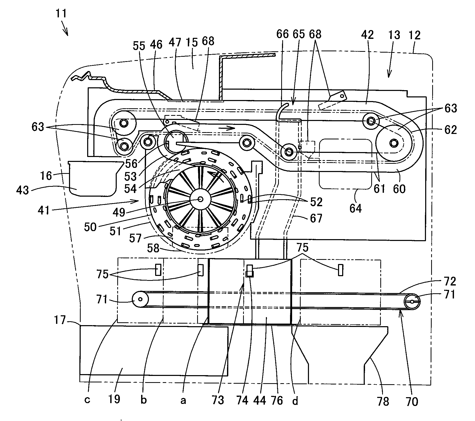
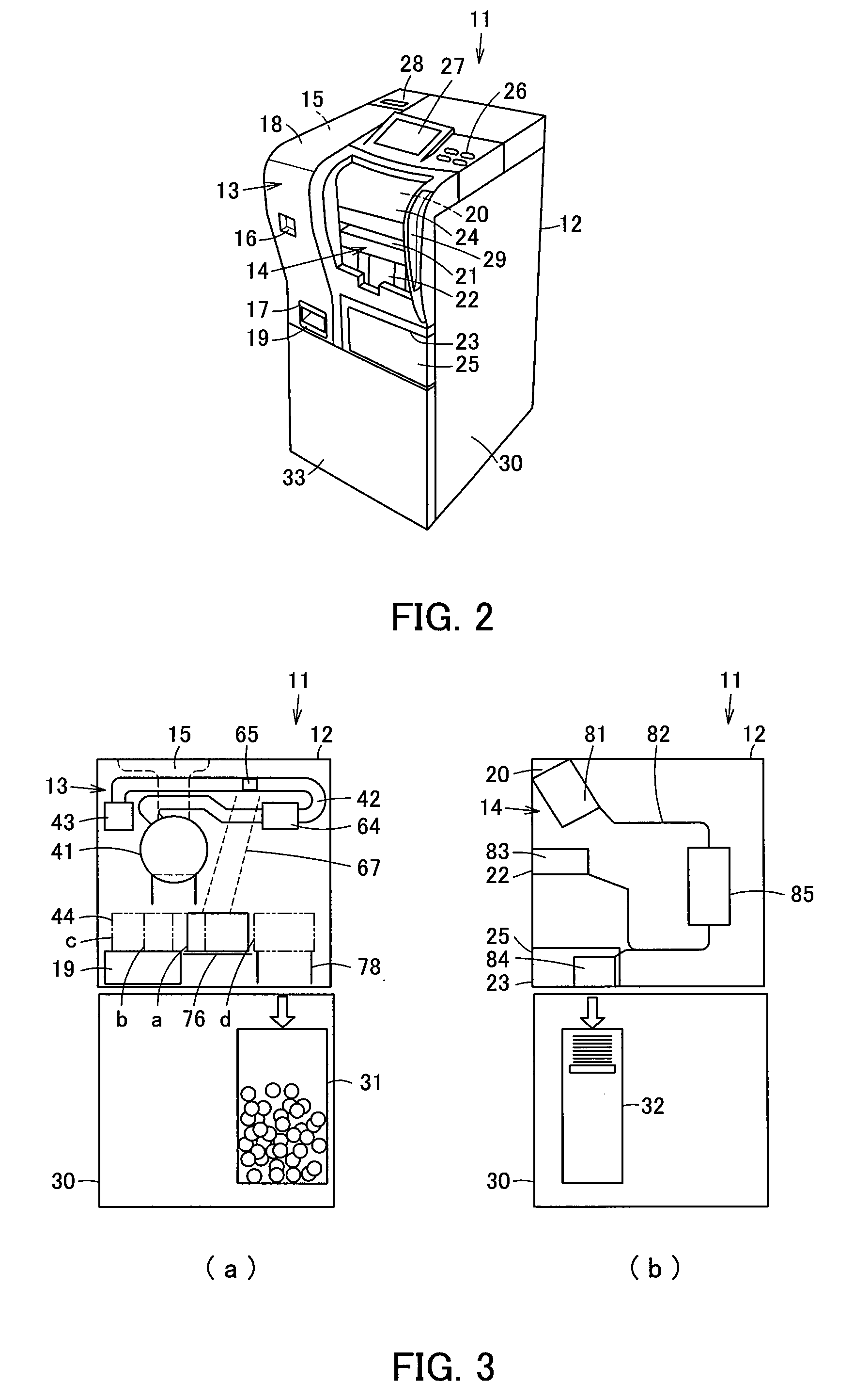
[0030]With the coin processing unit according to the present invention, the stopping positions of the escrow unit include an escrow position where the coins diverted from the transport path to be escrowed are received by the escrow unit, an ejection position where the coins dropped and released from the holding and feeding unit are received by the escrow unit, a returning position where the coins escrowed in the escrow unit are dropped to the coin returning unit, and a storing position where the coins escrowed in the escrow unit are dropped to the coin storing unit. Therefore, it becomes possible to move the escrow unit to the ejection position and to drop and release the coins from the holding and feeding unit and subsequently to move the escrow unit to the returning position so that the coins are dropped to the coin returning unit to be collectively returned. Therefore, it becomes possible to quickly respond to returning of coins in the holding and feeding unit when an unsuccessful feed from the holding and feeding unit due to cancellation of depositing process or input of a large amount of coins occurs and to returning of a
foreign object that remains in the holding and feeding unit without increasing the size of a unit even in a case where the unit can deposit a large amount of coins at one time. At the same time, operation efficiency can be improved.
[0031]With the coin processing unit according to the present invention, any two of the positions of the escrow position where coins diverted from the transport path to be escrowed are received by the escrow unit, the ejection position where the coins dropped and released from the holding and feeding unit are received by the escrow unit, the returning position where the coins escrowed in the escrow unit are dropped to the coin returning unit, and the storing position where the coins escrowed in the escrow unit are dropped into the coin storing unit are in one same position. That is, the number of stopping positions of the escrow unit is set to be three and the escrow unit is moved to each of these positions to allow the coins in the holding and feeding unit to be dropped and released to the escrow unit, so that the coins can be dropped to the coin returning unit from the escrow unit to be collectively returned. Therefore, it becomes possible to quickly respond to returning of coins in the holding and feeding unit when an unsuccessful feed from the holding and feeding unit due to cancellation of depositing processor input of a large amount of coins occurs and to returning of a
foreign object that remains in the holding and feeding unit without increasing the size of a unit even in a case where the unit can deposit a large amount of coins at one time. At the same time, operation efficiency can be improved.
[0032]With the coin processing unit according to the present invention, any three of the positions of the escrow position where coins diverted from the transport path to be escrowed are received by the escrow unit, the ejection position where the coins dropped and released from the holding and feeding unit are received by the escrow unit, the returning position where the coins escrowed in the escrow unit are dropped to the coin returning unit, and the storing position where the coins escrowed in the escrow unit are dropped into the coin storing unit are in one same position. That is, the number of stopping positions of the escrow unit is set to be two and the escrow unit is moved to each of the positions to allow the coins in the holding and feeding unit to be dropped and released to the escrow unit, so that the coins can be dropped to the coin returning unit from the escrow unit to be collectively returned. Therefore, it becomes possible to quickly respond to returning of coins in the holding and feeding unit when an unsuccessful feed from the holding and feeding unit due to cancellation of depositing process or input of a large amount of coins occurs and to returning of a foreign object that remains in the holding and feeding unit without increasing the size of a unit even in a case where the unit can deposit a large amount of coins. At the same time, operation efficiency can be improved.
[0033]With the coin processing unit according to the present invention, any two of the positions of the escrow position where coins diverted from the transport path are received by the escrow unit, the ejection position where the coins dropped and released from the holding and feeding unit are received by the escrow unit, the returning position where the coins escrowed in the escrow unit are dropped to the coin returning unit, and the storing position where the coins escrowed in the escrow unit are dropped into the coin storing unit are in one same position while the remaining two positions are also in one same position. That is, the number of stopping positions of the escrow unit is set to be two and the escrow unit is moved to each of the positions to allow the coins in the holding and feeding unit to be dropped and released to the escrow unit so that the coins can be dropped to the coin returning unit from the escrow unit to be collectively returned. Therefore, it becomes possible to quickly respond to returning of coins in the holding and feeding unit when an unsuccessful feed from the holding and feeding unit due to cancellation of depositing process or input of a large amount of coins occurs and to returning of a foreign object that remains in the holding and feeding unit without increasing the size of a unit even in a case where the unit can deposit a large amount of coins. At the same time, operation efficiency can be improved.


