Fuel cell hydrocarbon reformer having rapid transient response and convective cooling

Inactive Publication Date: 2010-02-18
DELPHI TECH INC
View PDF0 Cites 4 Cited by
  • Summary
  • Abstract
  • Description
  • Claims
  • Application Information

AI Technical Summary

Benefits of technology

[0007]Briefly described, the present invention comprises a catalyst brick concentrically disposed within a reformer tube which itself is disposed concentrically within an off-spaced housing, thereby defining an annular flow space between the reformer tube and the housing for air entering a fuel-air mixing zone ahead of the catalyst brick. The catalyst brick is sustained within the reformer tube by minimal mounting material; thus, most of the side of the catalyst brick is exposed for radial radiative heat transfer to the reformer tube and hence to cooling air in the annular flow space. Preferably, the forward portion of the mounting material is formed of a highly conductive material such as wire rope to provide a high level of radial conductive cooling of the entry portion of the catalyst brick which is known in the art to suffer degradation from localized overheating during catalysis. Preferably, the hot reformate exiting the catalyst sees reduced heat exchange with the incoming air flow compared to the prior art. Thus, incoming air can convectively cool the longitudinal side of the catalyst brick and allowing for reduced temperature of the face of the catalyst brick, thus increasing the working life of the catalyst brick while providing for more complete and more rapid fuel vaporization and hence more rapid startup of the reformer and associated fuel cell system.

Problems solved by technology

Inhomogeneous mixtures can lead to decreased reforming efficiency and reduced reformer catalyst durability through coke / soot formation on the catalyst and thermal degradation from local hot spots.
Fuel vaporization is especially challenging under reformer cold-start and warm-up conditions.

Method used


Image

  • Fuel cell hydrocarbon reformer having rapid transient response and convective cooling
  • Fuel cell hydrocarbon reformer having rapid transient response and convective cooling
  • Fuel cell hydrocarbon reformer having rapid transient response and convective cooling

Examples


Embodiment Construction

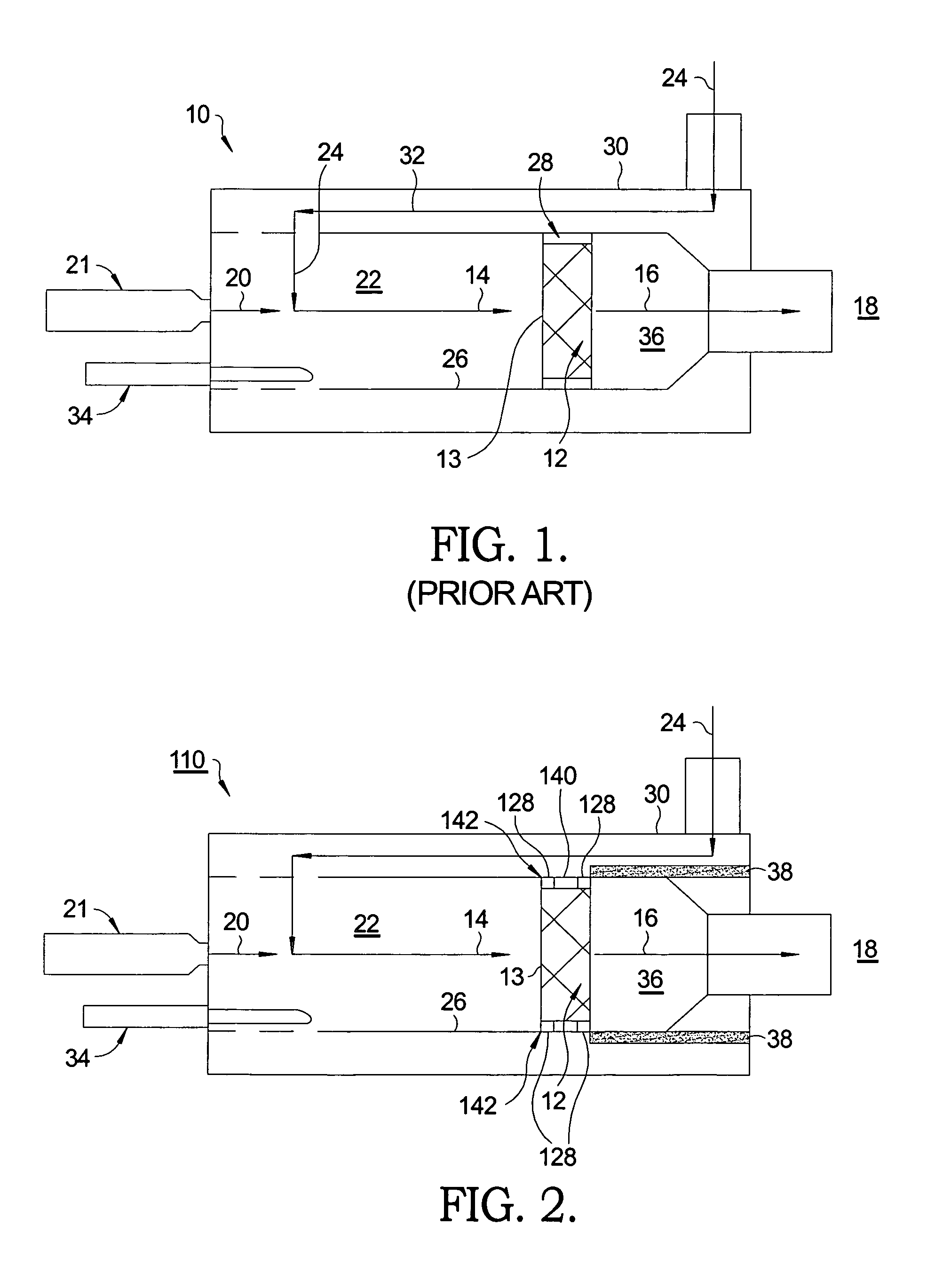
[0013]Referring to FIG. 1, a typical prior art catalytic hydrocarbon reformer 10, such as used for supplying reformate to a SOFC system, is shown. Reformer 10 comprises a catalytic element 12, typically a porous or channeled monolithic element known in the art as a “brick”, for converting a mixture 14 of hydrocarbons and oxygen to a reformate gas 16 containing molecular hydrogen and carbon monoxide. Reformate typically is used as a fuel in the SOFC 18 to generate electricity and heat. Fuel 20 is injected by a fuel injector 21 into a mixing zone 22 where it mixes with incoming air 24 to form mixture 14. Catalytic element 12 is mounted within a typically cylindrical reformer tube 26 from which element 12 is sustained and centered by a material 28 that completely surrounds the reforming catalyst. An outer housing 30 defines an annular space 32 for passage of incoming air 24. An igniter 34 extends into mixing zone 22 for ignition of mixture 14 during cold startup as described below.

[001...


PUM

PropertyMeasurementUnit
Flow rateaaaaaaaaaa
Electrical conductoraaaaaaaaaa
Heataaaaaaaaaa

Abstract

A catalytic hydrocarbon reformer comprising a catalyst concentrically disposed within a reformer tube surrounded by an annular flow space for air entering a fuel-air mixing zone ahead of the catalyst. The catalyst is sustained by minimal insulative mounting material so that most of the side of the catalyst is exposed for radial radiative heat transfer to the reformer tube for cooling by air in the annular flow space. The forward portion of the mounting material preferably is formed of a thermally-conductive material to provide radial conductive cooling of the entry of the catalyst to prevent overheating during catalysis. The incoming air flow is protected from heat exchange with hot reformate exiting the catalyst, allowing for convective cooling of the catalyst side and greater cooling of the catalyst face, thus increasing the working life of the catalyst while providing for rapid startup of the reformer and associated fuel cell system.

Description

TECHNICAL FIELD[0001]The present invention relates to catalytic hydrocarbon reformers for providing hydrogen and carbon monoxide fuels; more particularly, to such reformers wherein incoming fuel and air are heated by extracting heat from formed reformate exiting the reformer; and most particularly, to a reformer wherein heating of incoming air is accomplished by extraction mostly of heat from the catalytic element itself.BACKGROUND OF THE INVENTION[0002]Catalytic hydrocarbon reformers for converting air and hydrocarbon fuels into molecular hydrogen and carbon monoxide (reformate) as gaseous fuels for use in, for example, solid oxide fuel cells (SOFCs) are well known.[0003]Fuel-air mixture preparation in catalytic reformers is a key factor in fuel efficiency and reformer life. Inhomogeneous mixtures can lead to decreased reforming efficiency and reduced reformer catalyst durability through coke / soot formation on the catalyst and thermal degradation from local hot spots.[0004]Complete...

Claims


Application Information

Patent Timeline
IPC IPC(8): H01M8/06H01M8/10B01J8/00
CPCB01J19/2485B01J2219/00117B01J2219/00155C01B3/382C01B3/386C01B2203/0244Y02E60/525C01B2203/0844C01B2203/0883H01M8/0618H01M2008/1293Y02E60/50Y02E60/36C01B2203/0261
Inventor RAVENDA, FRANCOISVALENTE, PATRICKKIRWAN, JOHN E.RICCI-OTTATI, GIULIO A.
Owner DELPHI TECH INC
Why Eureka
Try Eureka