
Hay bale collection and stacking system

a stacking system and bale collection technology, applied in the field of hay bale collection and stacking system, can solve the problems of undesirable methods, difficult to move these bales with purely manual labor, and inability to meet the needs of hay bale collection and stacking, and achieve the effect of simple, reliable and robust, and prevent malfunction

Active Publication Date: 2010-02-18
RENNIE JOHN LIONEL
View PDF26 Cites 4 Cited by
  • Summary
  • Abstract
  • Description
  • Claims
  • Application Information

AI Technical Summary

Benefits of technology

[0010]Accordingly, it is the object of the present invention to provide a hay bale collection and stacking system requiring only one operator who does not have to exit their tractor.
[0011]It is another object of the present invention to provide a hay bale stacking and collection system that can load multiple stacks of hay bales onto one flatbed trailer.
[0012]It is still a further object of the present invention to provide a hay bale stacking and collection system that can offload all hay bales in an efficient manner.
[0013]It is yet another object of the present invention to provide a hay bale stacking system that is simple, reliable and robust in order to prevent malfunction.

Problems solved by technology

It is well known that moving these bales with purely manual labor is very difficult and as a result a mechanical apparatus to retrieve, transport and unload these most hay bales is required.
This method for the collection and stacking of hay bales is undesirable as it requires the labor of two operators and requires two pieces farm equipment.
While this collection method can eliminate a second operator, this method is undesirable as it is time consuming and laborious for one person to complete.
Furthermore, once all hay bales have been collected and transported to a desired unloading or storage area, the process of offloading any hay bales from a flat bed trailer requires a forklift or other appropriate lifting equipment and like the loading processes described above is time-consuming.
Further still, forklifts or other lifting equipment will often cause damage to hay bales.
For example, a forklift may pierce the hay bale or sever any attachments holding the bale together such that additional work may be required to repair or remove damaged bales.
Often forklifts and other appropriate lifting equipment handles bales roughly resulting in tears, punctures or the like that inhibit the formation of silage, haylage or the like.

Method used


Image

  • Hay bale collection and stacking system
  • Hay bale collection and stacking system
  • Hay bale collection and stacking system

Examples


Embodiment Construction

System Overview

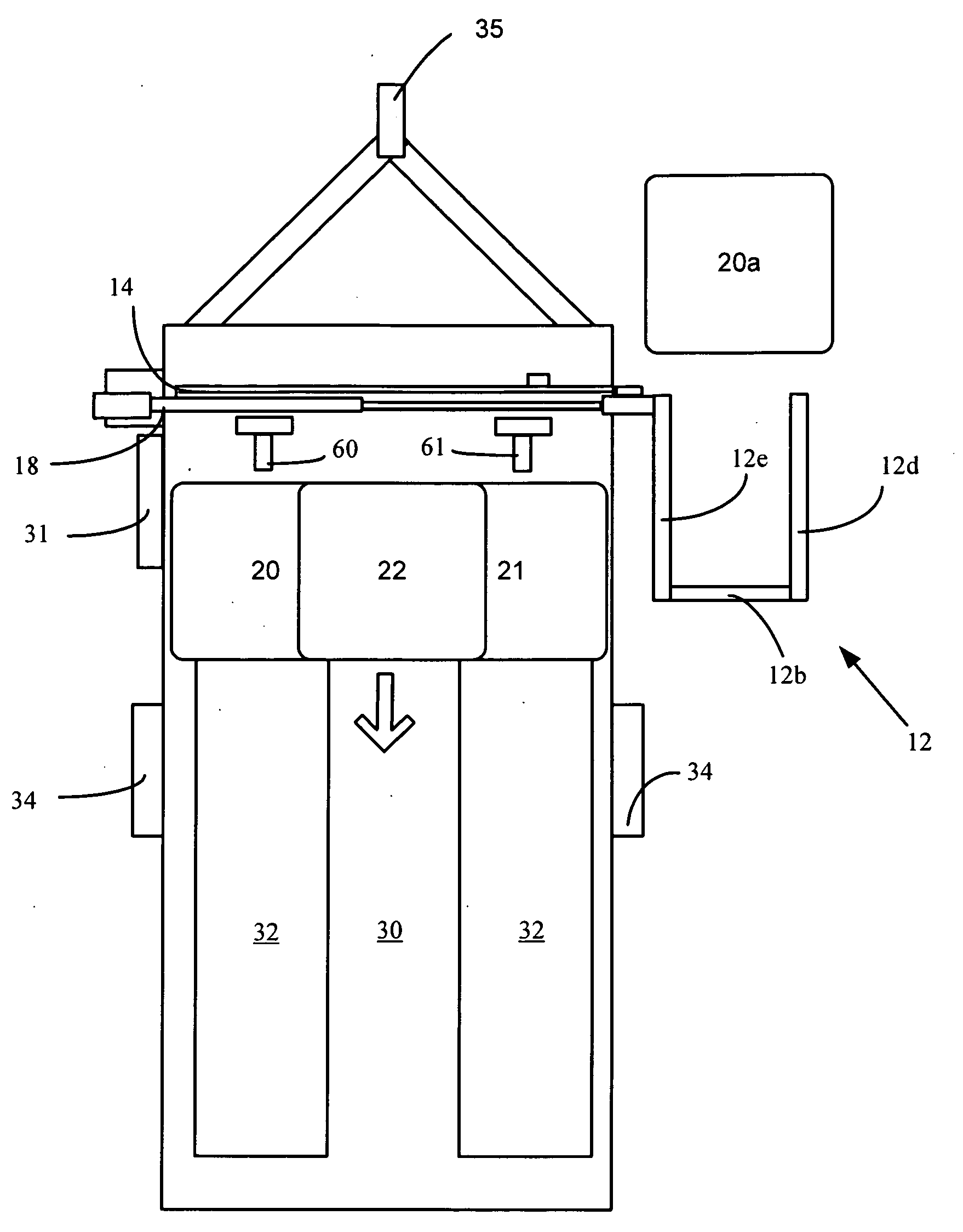
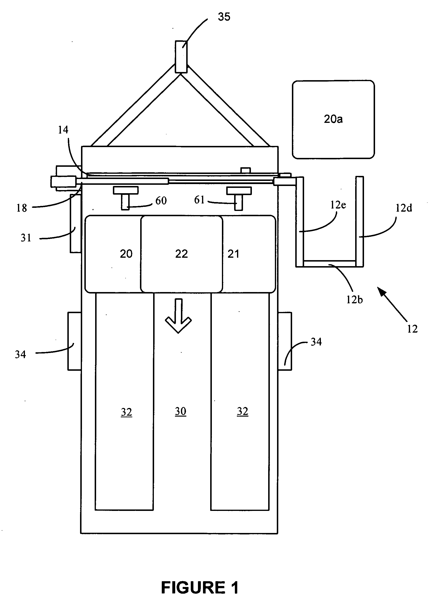
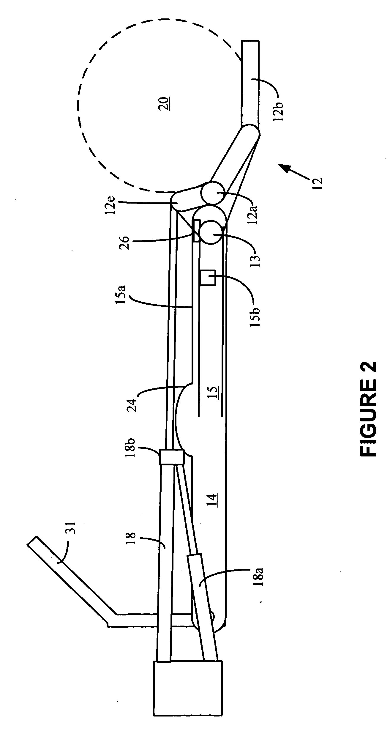
[0034]In accordance with the invention and with reference to the figures a hay bale collection and stacking system 10 is mounted on a flat bed trailer 30. The system generally includes cradle 12, pivot arm 14, main track 15, guide track 15a, latch 14b, one-way stop 26 and at least one hydraulic cylinder 18 mounted at the front end of the trailer 30. The trailer 30 includes wheels 34 and a trailer hitch 35 as known to those skilled in the art.

[0035]More specifically, and as shown schematically in FIGS. 1 and 2, the cradle 12 includes a track pivot wheel 13 able to slide and pivot within main track 15 and a cradle pivot wheel 12a able to roll along the guide track 15a that collectively enables both horizontal and vertical translation of the cradle from an outboard position as shown in FIG. 2 and various inboard positions as will be described in greater detail below and shown in FIGS. 3-11. As shown, a main hydraulic cylinder and piston 18 is operatively attached between...


PUM


Abstract

The present invention relates to an improved system for collecting and stacking round hay bales on a flat bed trailer, particularly for use in agricultural applications such as farming or the like.

Description

FIELD OF THE INVENTION[0001]The present invention relates to an improved system for collecting and stacking round hay bales on a flat bed trailer, particularly for use in agricultural applications such as farming or the like.BACKGROUND OF THE INVENTION[0002]It is common practice to transport hay and other agricultural products from one location to another as needed. Hay is usually baled into large cylindrical bales secured with twine that will often weigh several hundred kilograms depending on its size and moisture content. It is well known that moving these bales with purely manual labor is very difficult and as a result a mechanical apparatus to retrieve, transport and unload these most hay bales is required.[0003]In the past, the collection and stacking of hay bales is typically achieved with the use of various lifting and transporting equipment and the simultaneous work of at least two operators. For example, when collecting round hay bales in a field, one operator may drive a t...

Claims


Application Information

Patent Timeline
Patent Type & Authority Applications(United States)
IPC IPC(8): A01D85/00
CPCA01D85/005A01D90/083A01D87/122
Inventor RENNIE, JOHN LIONEL
Owner RENNIE JOHN LIONEL
Learn More