
Color sequential liquid crystal display and pixel circuit thereof

a liquid crystal display and color sequential technology, applied in the field of flat panel display technology, can solve the problems of color light only reaching through one-third of the space, lc response tends to be uneven, and light energy utilization efficiency declines, so as to increase the illumination time of each color in the color sequential lcd

Inactive Publication Date: 2010-02-18
AU OPTRONICS CORP
View PDF5 Cites 21 Cited by
  • Summary
  • Abstract
  • Description
  • Claims
  • Application Information

AI Technical Summary

Benefits of technology

[0011]The present invention provides a color sequential liquid crystal display (LCD) and a pixel circuit thereof. According to the present invention, a first voltage register and a second voltage register synchronously and alternately perform operations of outputting data signals and reading data signals so that the data signals of sub-frame periods are written and displayed simultaneously. As a result, the illumination time of each color in the color sequential LCD is increased.
[0027]In the present invention, the pixel circuit employs a structure having two voltage registers including the first voltage register and the second voltage register. When one of the voltage registers is reading data, the other voltage register is simultaneously displaying previously stored data signals on pixels to write data signals in the sub-frame and illuminate a signal-color light source so as to increase operation efficiency of the pixel circuit and prolong the illumination time of the pixels.

Problems solved by technology

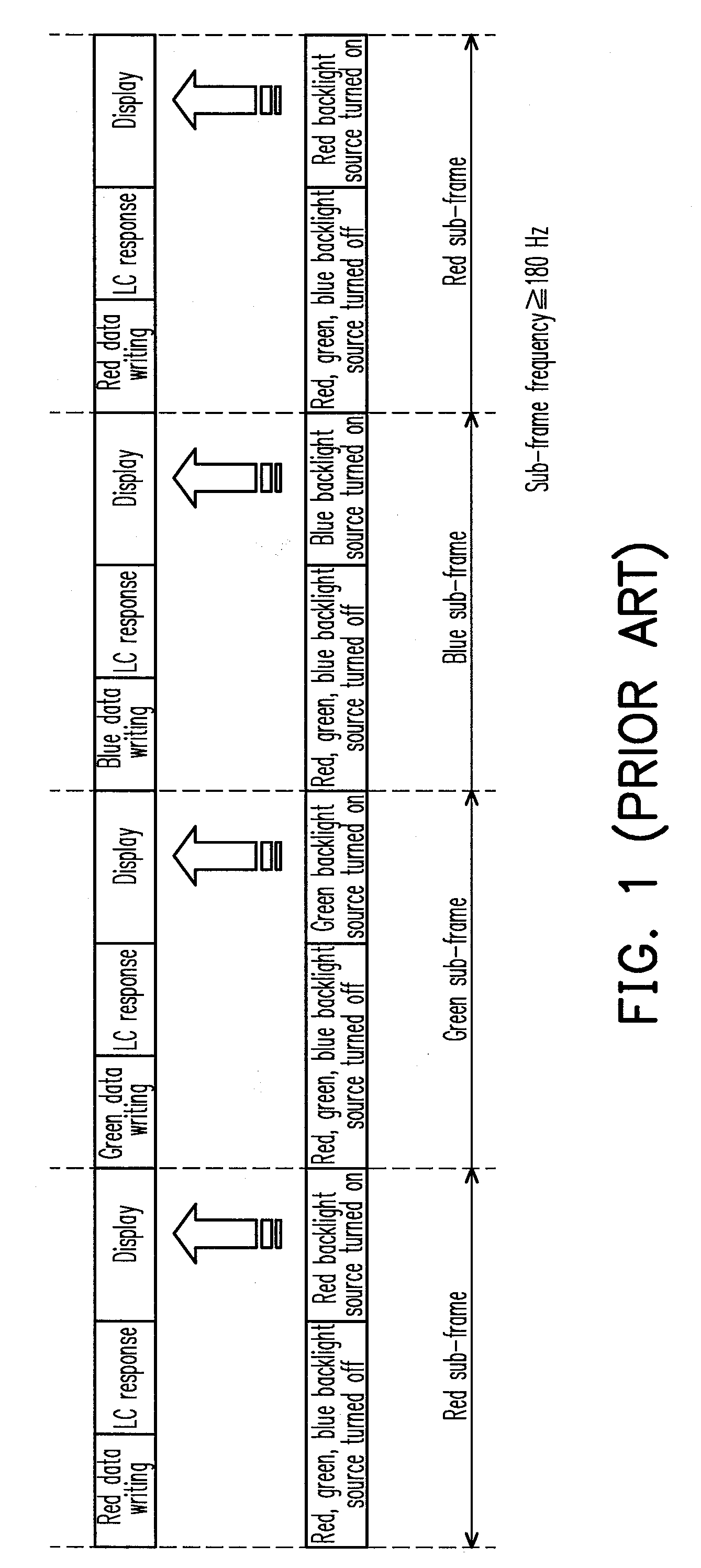
However, since a sub-pixel of each color can only let through the light energy of the color, the colored light can only penetrate through one-third of the space.
Moreover, since the color filters absorb light energies, the efficiency of light energy utilization would decline.
Consequently, the LC response tends to become uneven.
Accordingly, if the color sequential method is operated too slowly, color breakup will be occurred.

Method used


Image

  • Color sequential liquid crystal display and pixel circuit thereof
  • Color sequential liquid crystal display and pixel circuit thereof
  • Color sequential liquid crystal display and pixel circuit thereof

Examples


Embodiment Construction

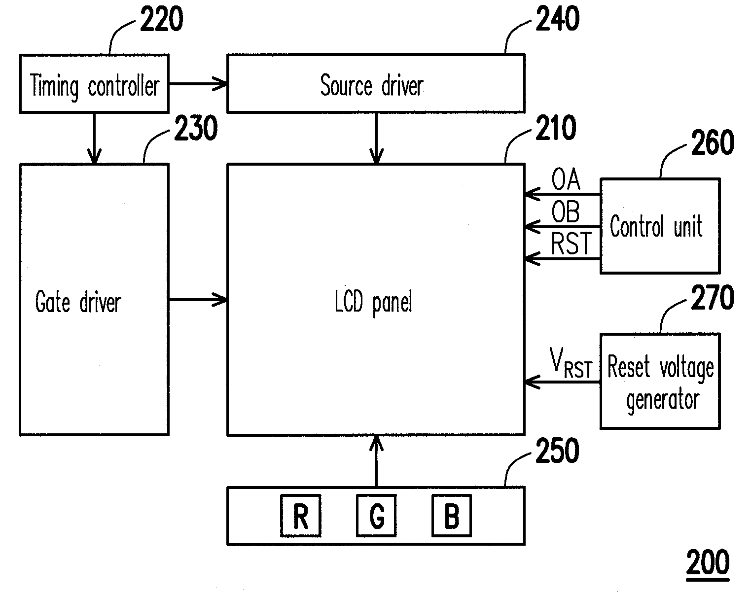
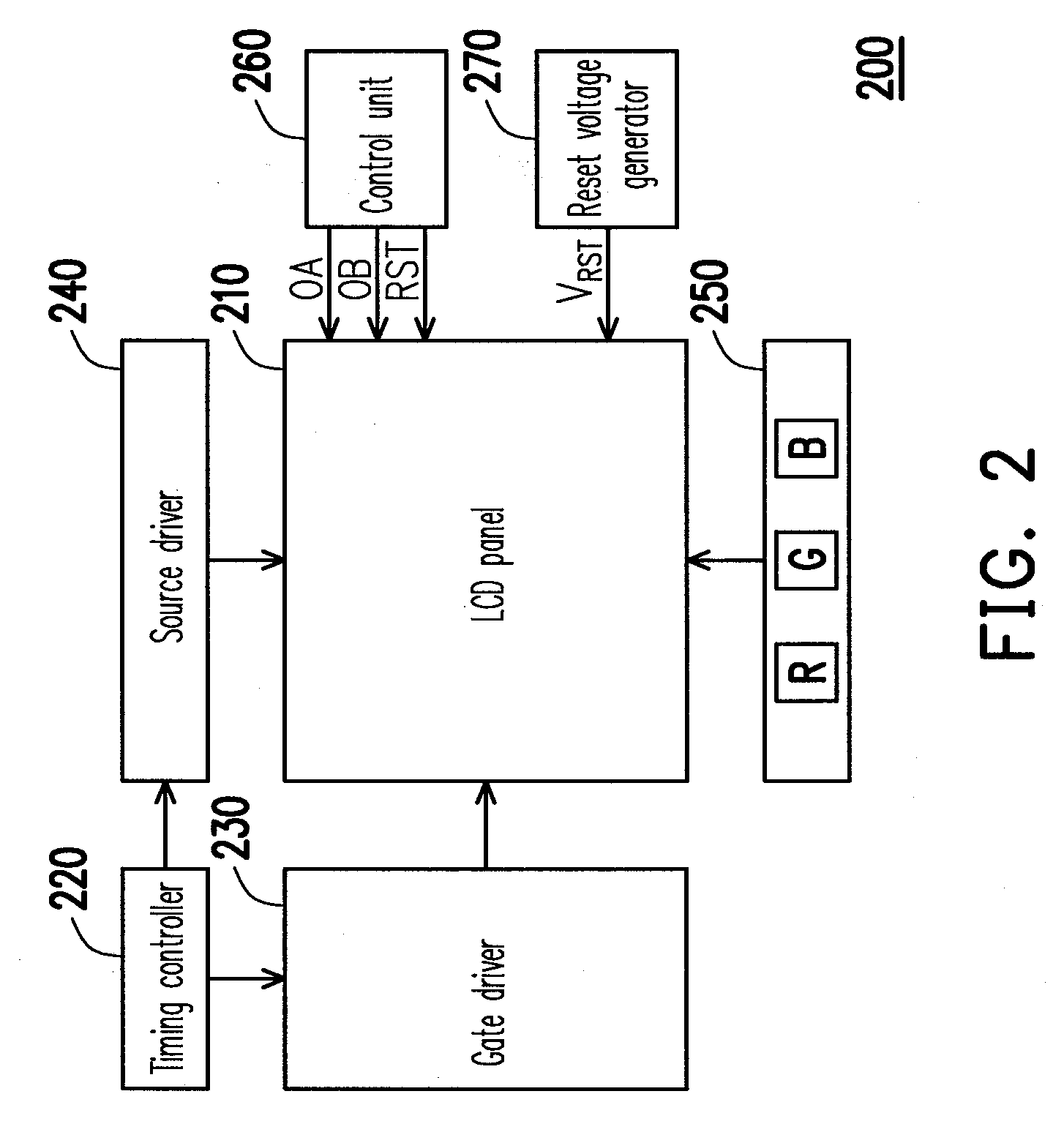
[0036]FIG. 2 is a system block diagram of a color sequential LCD 200 according to an embodiment of the present invention. Referring to FIG. 2, the color sequential LCD 200 includes an LCD panel 210, a timing controller 220, a gate driver 230, a source driver 240, a light-emitting diode (LED) backlight module 250, a control unit 260 and a reset voltage generator 270. The timing controller 220 is coupled to the gate driver 230 and the source driver 240 and provides a control signal to the gate driver 230 and the source driver 240. The gate driver 230 is coupled to the LCD panel 210 to sequentially provide scan signals to the LCD panel 210. The gate driver 240 is coupled to the LCD panel 210 to provide data signals to the LCD panel 210.

[0037]The LED backlight module 250 is disposed under the LCD panel 210 (or alternatively disposed at a side of light guide, not shown) to provide a red, a green and a blue single-color light sources respectively to the LCD panel 210 to achieve the color ...


PUM


Abstract

A color sequential liquid crystal display and a pixel circuit thereof are provided. The pixel circuit includes a first and a second sampling switches, a first and a second voltage registers, a first and a second output switches, a liquid crystal (LC) capacitor, and a reset switch. The first voltage register is coupled to the first sampling and the first output switches to register a first sampling voltage during a first sub-frame, and output the first sampling voltage to the LC capacitor during a second sub-frame. The second voltage register is coupled to the second sampling and the second output switches to register a second sampling voltage during the second sub-frame, and output the second sampling voltage to the LC capacitor during the first sub-frame. The reset switch is coupled to the LC capacitor to transmit a reset voltage to the LC capacitor between the first and second sub-frame periods.

Description

CROSS-REFERENCE TO RELATED APPLICATION[0001]This application claims the priority benefit of Taiwan application serial no. 97131426, filed on Aug. 18, 2008. The entirety of the above-mentioned patent application is hereby incorporated by reference herein and made a part of this specification.BACKGROUND OF THE INVENTION[0002]1. Field of the Invention[0003]The present invention relates to a flat panel display technology and particularly to a color sequential liquid crystal display and a pixel circuit thereof.[0004]2. Description of Related Art[0005]As technologies in optoelectronics and semiconductors advance, flat panel displays also flourish accordingly. Among various flat panel displays, the liquid crystal display (LCD) has become the mainstream in the market because of its superior characteristics, such as high space utilization, low power consumption, no radiation and low electromagnetic disturbance. Generally, the conventional LCD panel displays the colors and luminance an image ...

Claims


Application Information

Patent Timeline
IPC IPC(8): G09G5/00G09G3/36
CPCG09G2310/0235G09G2310/063G09G2300/0842G09G3/36G09G3/3659G09G2320/0242
Inventor CHEN, CHUNG-CHUNLI, CHUN-HUAI
Owner AU OPTRONICS CORP
Learn More