Variable capacitor employing MEMS technology
a variable capacitor and capacitor technology, applied in the field of variable capacitors, can solve the problems of difficult to make common passive components such as capacitors and inductors, and increasing the number of components, along with the increase of the frequency band
- Summary
- Abstract
- Description
- Claims
- Application Information
AI Technical Summary
Benefits of technology
Problems solved by technology
Method used
Image
Examples
first exemplary embodiment
[0053]Outline Configuration of Variable Capacitor
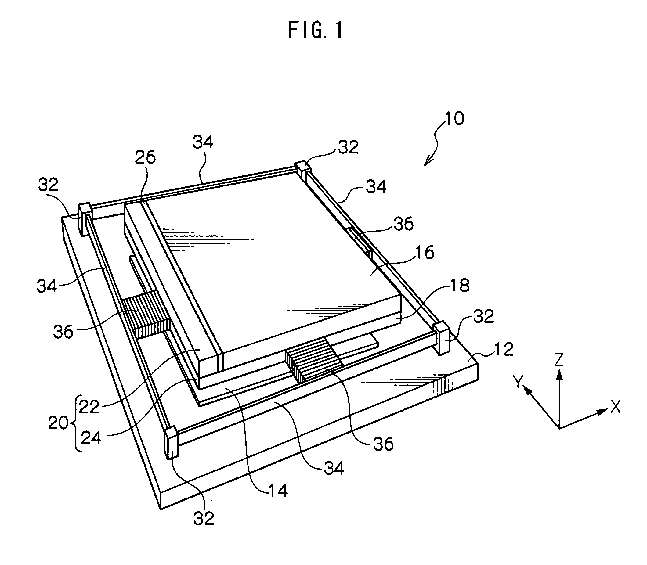
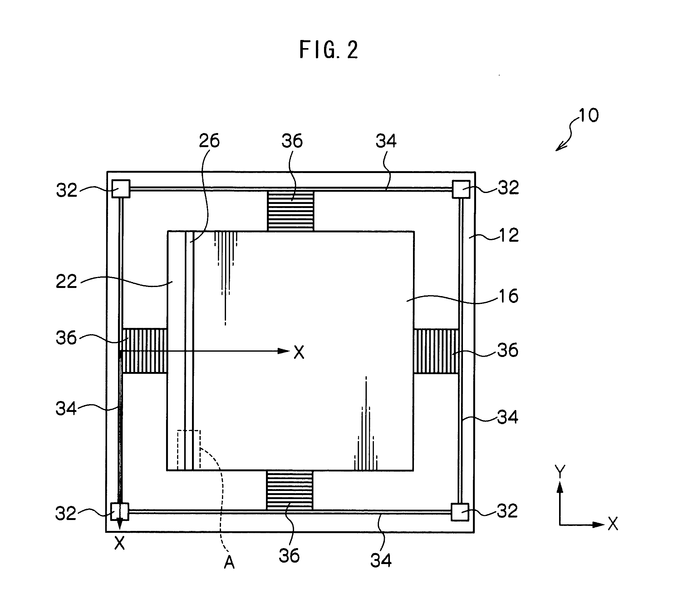
[0054]First, a simple explanation will be given of a configuration of a variable capacitor, with reference to FIG. 1 to FIG. 3. FIG. 1 is a perspective view showing the external appearance of a variable capacitor according to a first exemplary embodiment of the present invention. FIG. 2 is a plan view of a variable capacitor, as seen from the fixed electrode. FIG. 3 is a side view of a variable capacitor.
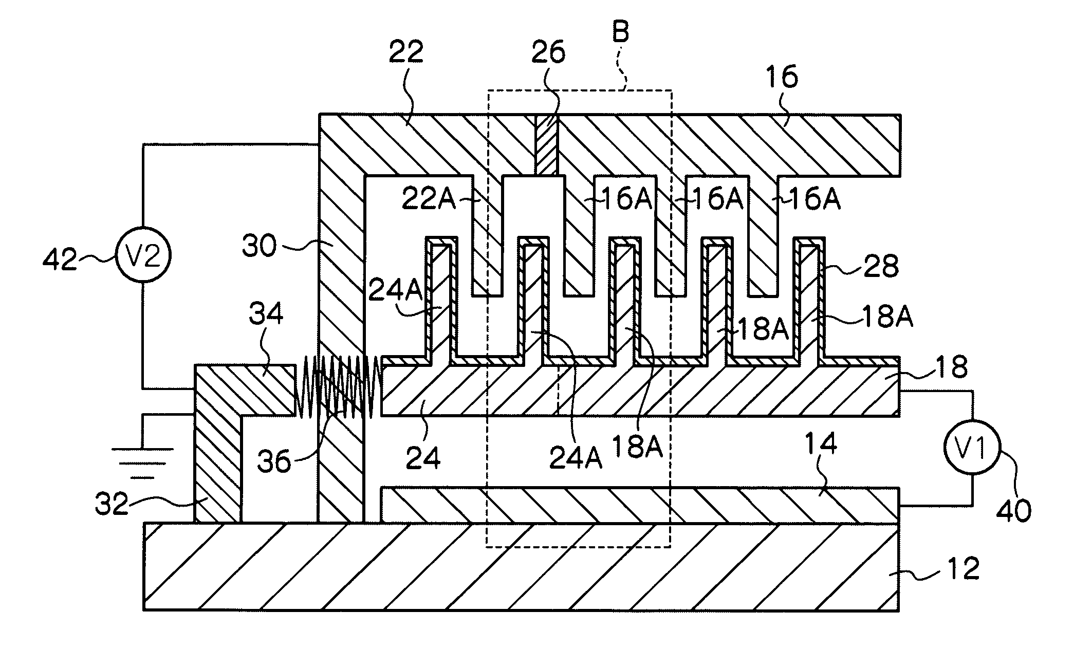
[0055]A variable capacitor 10 is equipped with: a support substrate 12 configured from a semiconductor such as silicon or the like; a drive electrode 14 disposed on the support substrate 12; a fixed electrode 16 disposed so as to face the drive electrode 14 with a separation therebetween; a movable electrode 18, disposed retained moveably between the drive electrode 14 and the fixed electrode 16; and a brake capacitor 20, serving as a vibration prevention portion for preventing vibration after movement of the movable electrode 18. The...
second exemplary embodiment
[0113]FIGS. 14A to 14C are enlarged diagrams of portions of a variable capacitor according to a second exemplary embodiment of the present invention. FIG. 14A is a diagram corresponding to FIG. 6 of the first exemplary embodiment. A variable capacitor 10A according to the second exemplary embodiment is of similar configuration to that of the first exemplary embodiment, except in that a movable drive electrode 52 is formed to the back face of the movable electrode 18 to which the lower portion brake electrode 24 is attached, with an insulating layer 50 interposed therebetween. Therefore similar portions will be allocated the same reference numerals and part of the explanation thereof will be omitted.
[0114]As shown in FIG. 14A, a movable electrode 18 and a lower portion brake electrode 24 are integrally formed from an electrically-conductive material, as a member of rectangular shape in plan view. The portion of this member facing a fixed electrode 16 is the movable electrode 18, and ...
third exemplary embodiment
[0135]FIG. 17 is a side view of a variable capacitor according to a third exemplary embodiment of the present invention. FIGS. 18A to 18C are enlarged diagrams of portions of a variable capacitor according to the third exemplary embodiment of the present invention. FIG. 17 is a diagram corresponding to FIG. 3 of the first exemplary embodiment. FIG. 18A is a diagram corresponding to FIG. 6 of the first exemplary embodiment. A variable capacitor 10B according to the third exemplary embodiment is of similar configuration to that of the first exemplary embodiment, except in that a dielectric layer 60 is provided on the support substrate 12 so as to cover the drive electrode 14. Therefore similar portions will be allocated the same reference numerals and part of the explanation thereof omitted
[0136]In a similar manner to in the first exemplary embodiment, a drive electrode 14 of a rectangular shape in plan view that is slightly smaller than a support substrate 12, is formed at the middle...
PUM
 Abstract
Description
Claims
Application Information
 - R&D
- Intellectual Property
- Life Sciences
- Materials
- Tech Scout
- Unparalleled Data Quality
- Higher Quality Content
- 60% Fewer Hallucinations
Browse by: Latest US Patents, China's latest patents, Technical Efficacy Thesaurus, Application Domain, Technology Topic, Popular Technical Reports.
© 2025 PatSnap. All rights reserved.Legal|Privacy policy|Modern Slavery Act Transparency Statement|Sitemap|About US| Contact US: help@patsnap.com


