
Hot cathode and ion source including the same

a technology of ion source and hot cathode, which is applied in the manufacture of electrode systems, electric discharge tubes/lamps, instruments, etc., can solve the problems of short lifetime of hot cathode, short internal conductor meltdown time, and short hot cathode life, so as to prolong the lifetime of internal conductor and suppress the temperature rise

Inactive Publication Date: 2010-02-18
NISSIN ION EQUIP CO LTD
View PDF4 Cites 15 Cited by
  • Summary
  • Abstract
  • Description
  • Claims
  • Application Information

AI Technical Summary

Benefits of technology

[0006]Exemplary embodiments of the present invention provide a hot cathode and ion source including the same, which can suppress the temperature rise of an internal conductor of a hot cathode having a coaxial structure, thereby prolonging the lifetime of the internal conductor, and therefore that of the hot cathode.
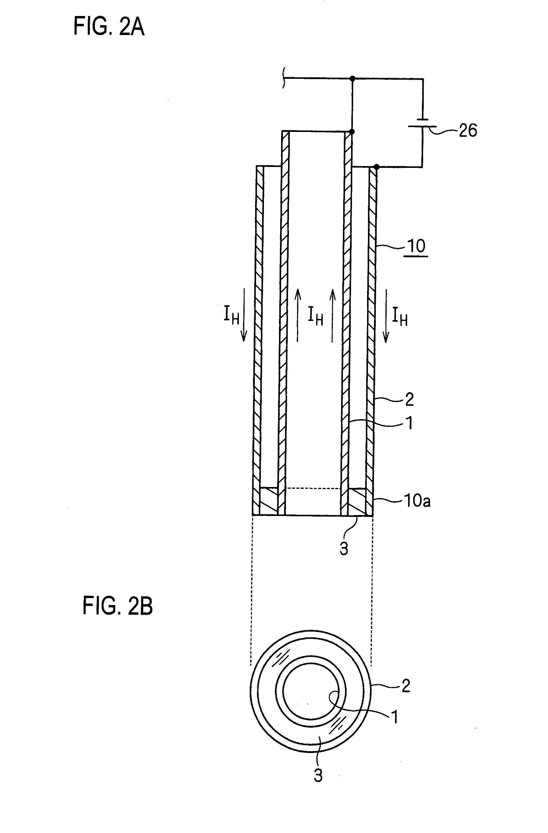
[0008]In the hot cathode, since the internal conductor is hollow, the size of the internal conductor can be increased as compared with the case of a solid internal conductor, while suppressing increase of the mass and sectional area of the internal conductor. As a result, the concentration of heat per unit surface area in the internal conductor can be reduced, and the temperature rise of the internal conductor can be suppressed.
[0012]According to the hot cathode of the exemplary embodiment of the invention, since the internal conductor is hollow, the size of the internal conductor can be increased as compared with the case of a solid internal conductor, while suppressing increase of the mass and sectional area of the internal conductor. As a result, the concentration of heat per unit surface area in the internal conductor can be reduced, and the temperature rise of the internal conductor can be suppressed. Therefore, the lifetime of the internal conductor, and then that of the hot cathode can be prolonged.
[0013]Moreover, the exemplary embodiment of the invention attains the following effects. Since the tip end portions of the internal and external conductors are electrically directly connected to each other without using the connection conductor, the volume of a tip end of the hot cathode can be reduced as compared with the case where the connection conductor is used. As a result, the thermal capacity of the hot cathode can be lowered, and the time constant in the temperature control can be reduced, so that the responsiveness in the temperature control can be improved.
[0014]Furthermore, the exemplary embodiment of the invention attains the following further effects. Although the temperature of the internal conductor is made higher than that of the external conductor, the internal conductor has a high heat resistance because the internal conductor is made of a material which is higher in melting point than the external conductor. Therefore, the lifetime of the internal conductor, and then that of the hot cathode can be prolonged. Furthermore, the operating range of the hot cathode can be more widened.

Problems solved by technology

When the heating current is increased, therefore, the temperature of the internal conductor is raised higher than the melting point of the material constituting the internal conductor, thereby causing the possibility that the internal conductor is melted down in a short time.
Consequently, there is a problem in that the lifetime of the internal conductor, and therefore that of the hot cathode is short.

Method used


Image

  • Hot cathode and ion source including the same
  • Hot cathode and ion source including the same
  • Hot cathode and ion source including the same

Examples


Embodiment Construction

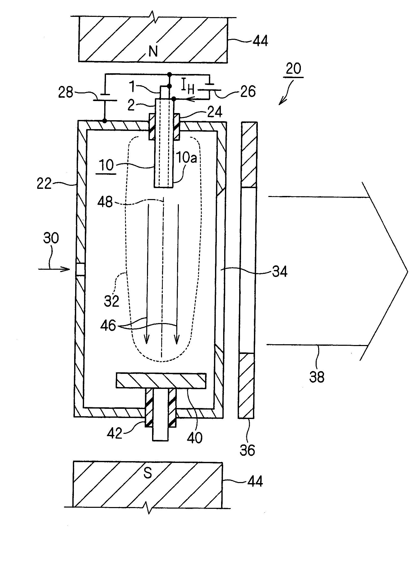
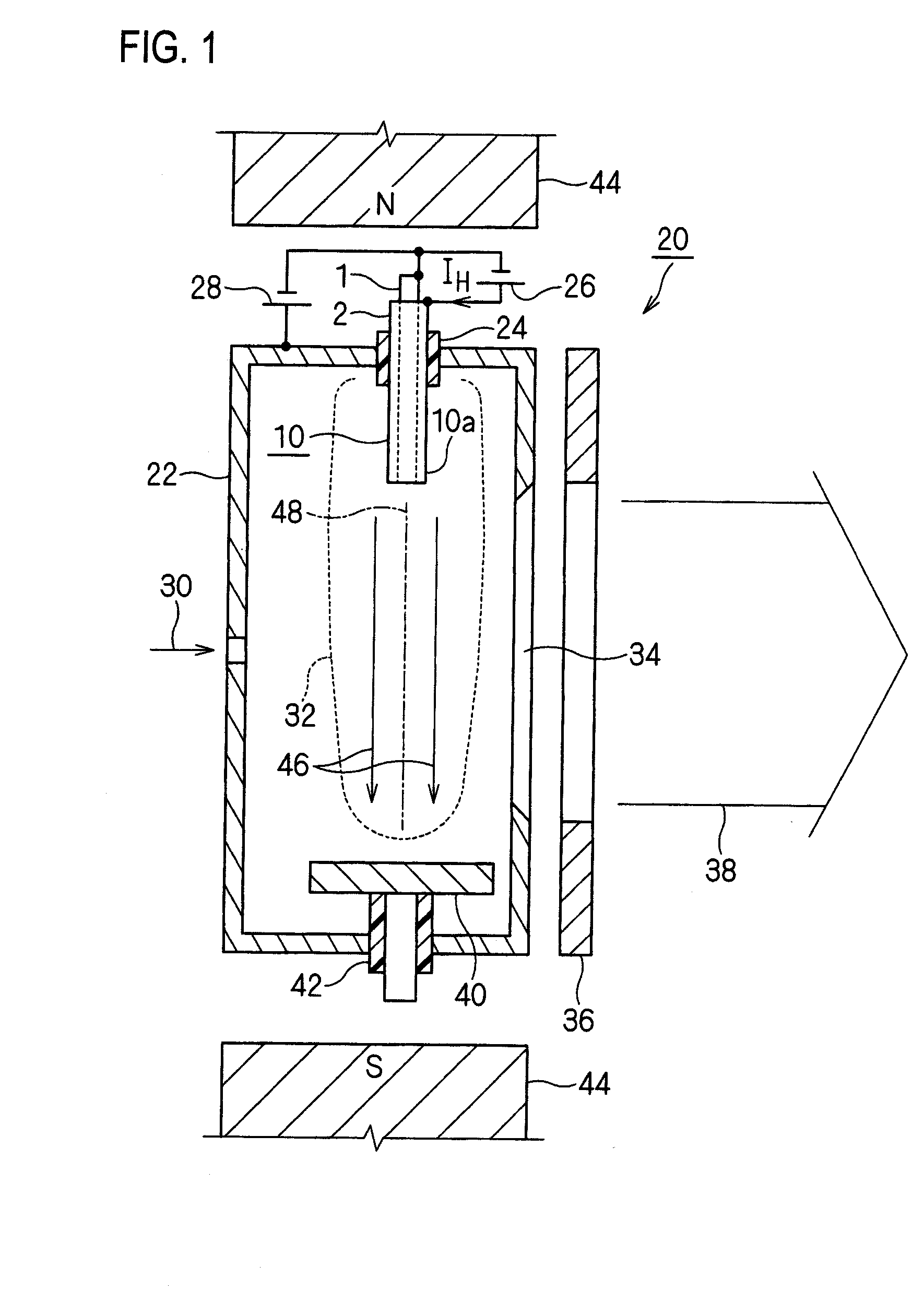
[0027]FIG. 1 is a schematic sectional view showing an embodiment of an ion source including the hot cathode of the invention. The ion source 20 includes a hot cathode 10 as a cathode for generating a plasma 32. Namely, the ion source 20 is configured so that thermal electrons are emitted from the hot cathode 10 into a plasma generating chamber 22 functioning also as an anode, an arc discharge is produced between the hot cathode 10 and the plasma generating chamber 22, a gas (including the case of vapor) 30 introduced into the plasma generating chamber 22 is ionized to generate the plasma 32, and an ion beam 38 is extracted from the plasma 32 by an extraction electrode system 36 through an ion extraction port 34.

[0028]In the embodiment, the ion extraction port 34 has a shape which is elongated in the vertical direction in FIG. 1, so that the ion beam 38 having a ribbon-like shape can be extracted from the ion source 20. More specifically, the ion extraction port 34 in the embodiment ...


PUM


Abstract

A hot cathode includes: a hollow external conductor; a hollow internal conductor which is placed coaxially inside the external conductor; and a connection conductor which electrically connects tip end portions of the conductors. A heating current is folded back through the connection conductor to flow in opposite directions in the external conductor and the internal conductor.

Description

TECHNICAL FIELD[0001]The present disclosure relates to a hot cathode which is to be used in, for example, an ion source for generating an ion beam, a plasma source for generating a plasma, or an electron beam source for generating an electron beam, and from which thermal electrons are emitted, and also to an ion source including the hot cathode.RELATED ART[0002]For example, Patent Reference 1 discloses a hot cathode which has a coaxial structure including: a tubular external conductor; a solid (filled or not hollowed) internal conductor (center conductor) that is placed coaxially inside the external conductor; and a connection conductor that electrically connects tip end portions of the external and internal conductors to each other, and in which the heating current is folded back through the connection conductor to flow in opposite directions in the external and internal conductors, and also an ion source including the hot cathode.[0003]According Patent Reference 1, the hot cathode...

Claims


Application Information

Patent Timeline
Patent Type & Authority Applications(United States)
IPC IPC(8): H01J27/00H01J9/02
CPCH01J1/16H01J3/027H01J3/04H01J2237/06308H01J37/065H01J37/08H01J27/08
Inventor MIYAMOTO, NAOKI
Owner NISSIN ION EQUIP CO LTD
Learn More