Eureka AIR delivers breakthrough ideas for toughest innovation challenges, trusted by R&D personnel around the world.

Soundproof type engine generator

a generator and soundproof technology, applied in the direction of machines/engines, mechanical equipment, combustion air/fuel air treatment, etc., can solve the problems of engine overheating to be disabled to operate, deteriorating the soundproofing effect of increasing the opening area, and affecting the operation of the engin

Inactive Publication Date: 2010-02-18
MITSUBISHI HEAVY IND LTD
View PDF3 Cites 25 Cited by
  • Summary
  • Abstract
  • Description
  • Claims
  • Application Information

AI Technical Summary

Benefits of technology

[0009]The present invention is a soundproof type engine generator in which an inverter, an engine fan, a alternator, an engine, a recoil fan, and a recoil starter are coaxially arranged in that order from nearest to farthest from a first air inlet. The present invention is characterized in that: a first cooling air passage is formed to allow cooling air sucked by the engine fan from the first air inlet to cool the inverter, the alternator an

Problems solved by technology

However, reduction of the opening area of the soundproof case causes decrease in an intake and a discharge of cooling air supplied into the soundproof case, whereby the engine overheats to be disabled to operate.
Conversely, increasing the opening area deteriorates a soundproofing effect.
On the other hand, downsizing the soundproof case makes an air passage therein narrower, so that the air passage is deteriorated in ventilation performance, and thus is not expected to exert a sufficient cooling effect.
For these reasons, it is inevitable to confront the reality that convenience in portability, reduction in weight, and reduction in size, which are required of a soundproof type generator, are difficult to achieve.
For this reason, cooling of the inverter unit and the fuel tank tends to be insufficient in this structure.
This leads to a heavier weight of the engine generator, and makes weight reduction thereof difficult.

Method used


Image

  • Soundproof type engine generator
  • Soundproof type engine generator
  • Soundproof type engine generator

Examples


Embodiment Construction

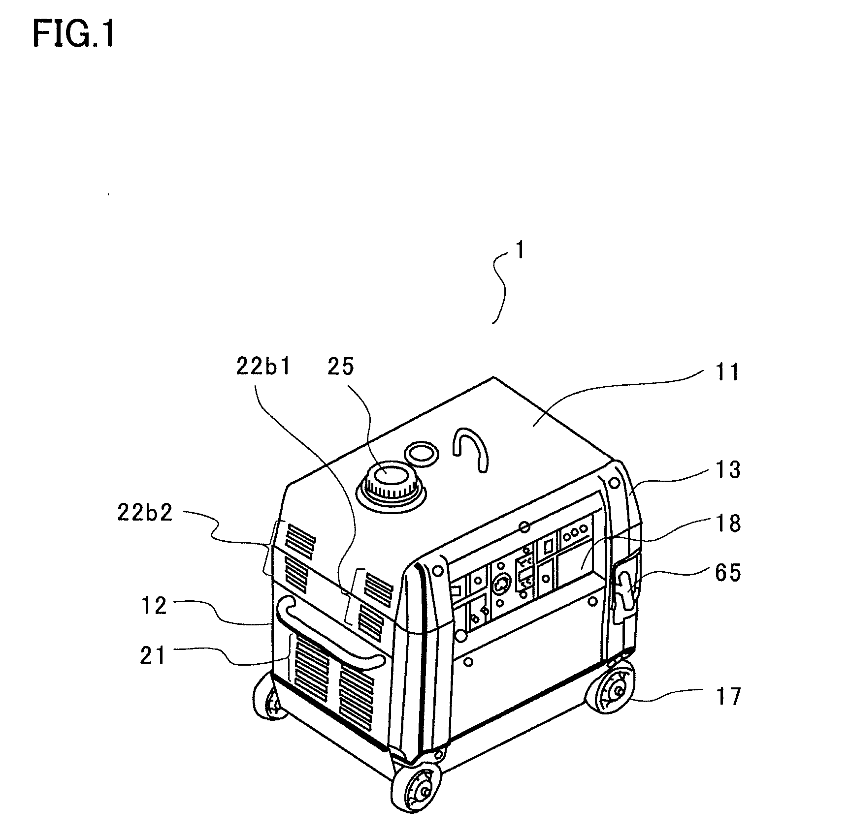
[0022]Description will be given of a perspective view, shown in FIG. 1, of a soundproof type engine generator 1 according to the present invention. Although an engine, a alternator and the like are covered by a soundproof case and cannot be seen, this configuration enhances a soundproof effect. The soundproof case is composed of a main frame 11, a left-side face cover 12, a front-face cover 13, a right-side face cover 15 (refer to FIG. 3) and a back-face cover 14 (refer to FIG. 3), the right-side face cover 15 and the back-face cover 14 existing behind the view.

[0023]In the left-hand side of the main frame 11, an air inlet 22b1 and an air inlet 22b2 are provided which form a second cooling air passage and a third cooling air passage, respectively. In an upper part of the main frame, there is a fuel tank cap 25, from which fuel is fed.

[0024]In the left-side face cover 12, a first air inlet 21 which forms a first cooling air passage is provided.

[0025]Through an opening of the front-fa...


PUM


Abstract

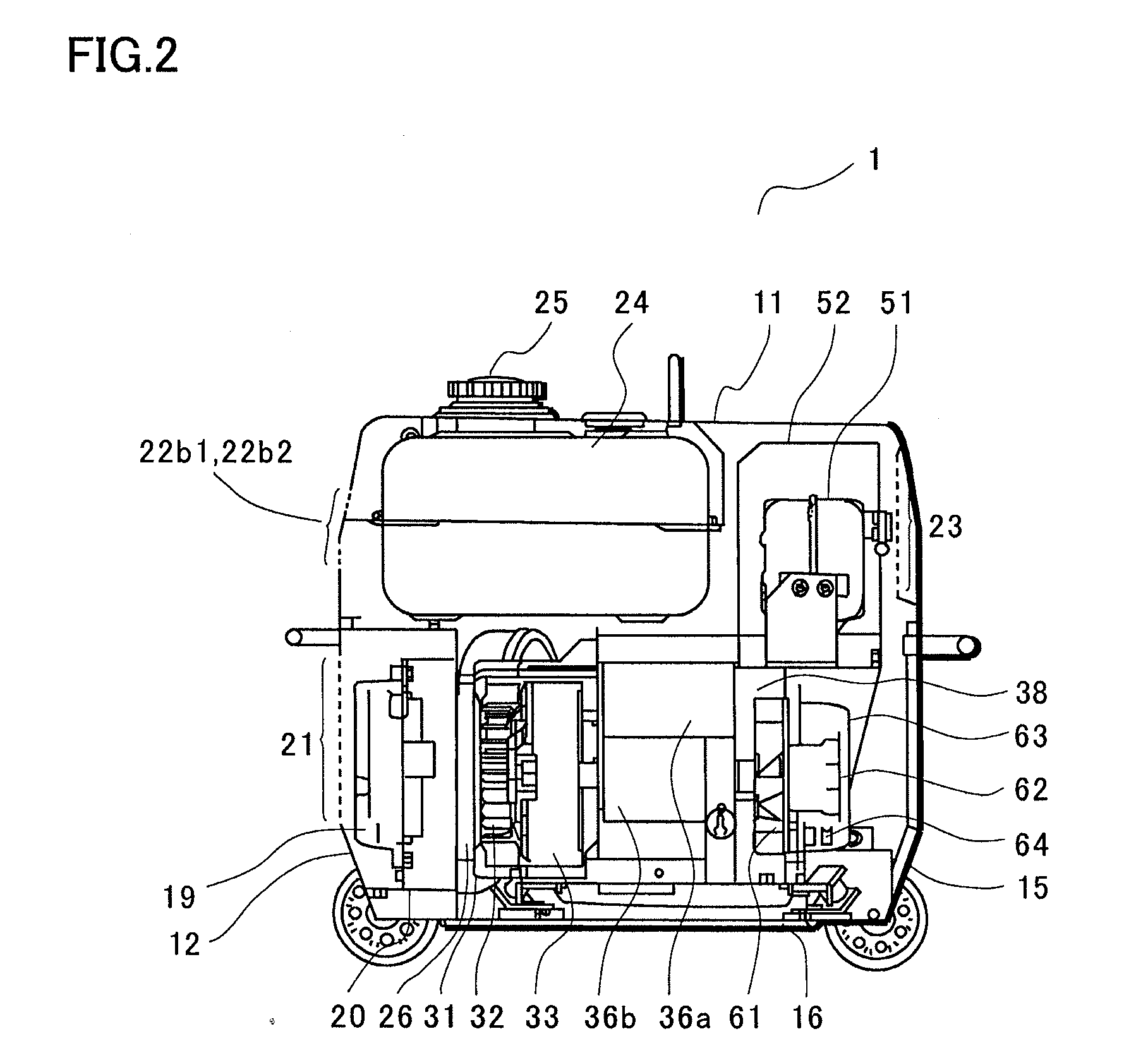
A small and lightweight sound-proof generator exhibiting sufficient cooling effect. An inverter (19), an engine fan (32), a power generating body (33), an engine (34), a recoil fan (61), a recoil starter (63) are coaxially arranged sequentially from a first inlet port side. A first cooling air passage for cooling inverter (19), the power generating body (33), and the engine (34) with cooling air sucked by the engine fan (32) from the inlet port (21), and second and third cooling air passage for cooling a space surrounded by an inverter containing box (20), an engine fan cover (31), an engine cover (36) and a muffler cover (52) and a soundproof case with cooling air sucked by the recoil fan (61) from inlet ports (21b1) and (21b2) are formed. Cooling air passed through the first cooling air passage and cooling air passed through the second and the third cooling air passages are merged and discharged from an outlet port after cooling a muffler.

Description

REFERENCE TO RELATED APPLICATIONS[0001]This application is a national stage application under 35 USC 371 of International Application No. PCT / JP2006 / 318682, filed Sep. 14, 2006, the contents of which are incorporated herein by reference.FIELD OF THE INVENTION [0002]The present invention relates to a compact and lightweight soundproof type engine generator which is covered with a soundproof case.BACKGROUND OF THE INVENTION [0003]An engine generator, which is an integrated system of a compact engine and an alternator driven by this engine, is highly portable, and thus suitable for use in urban areas. When intended to be used in an urban area, especially at night, this engine generator has to have a structure in which the entire system is covered with a soundproof case so as to suppress driving noise thereof as far as possible in consideration of an ambient environment. To further suppress leakage of the driving noise, it is necessary to reduce an opening area of the soundproof case as...

Claims


Application Information

Patent Timeline
IPC IPC(8): F02F1/34F01P7/04F02M35/02F02B77/13
CPCF01P1/06F02B63/047F02B63/04F01P2001/005
Inventor YAMASAKI, MASATOMATSUBATA, TERUAKIAWATA, HIROKI
Owner MITSUBISHI HEAVY IND LTD
Why Eureka
Eureka Blog
Learn More