Breech block for a drop-down barrel weapon

Inactive Publication Date: 2010-02-18
STEYR MANNLICHER
View PDF14 Cites 1 Cited by
  • Summary
  • Abstract
  • Description
  • Claims
  • Application Information

AI Technical Summary

Benefits of technology

[0007]The aim set by the invention is to provide a safety system for a drop-down barrel weapon with block lock, which is simpler, less susceptible to failure and is substantially safer than the known designs. This aim is achieved with the breech block of the aforementioned type, which is distinguished according to the invention in that a safety slide is guided in a transversely displaceable manner in a recess on the firing piece side of the breech block between a first position, in which it projects beyond the impact head of the firing pin in the impact area of the firing piece, and a second position, in which it is pulled back from the impact area of the firing piece, which recess is at least partially closed by a cover plate, wherein the cover plate has recesses for the impact head and the spacer head to pass through.
[0008]The invention proposes a novel safety system concept for the first time that is directly integrated into the breech block. This results in a particularly space-saving, encapsulated safety system that is less susceptible to failure and is directly in the impact area of the firing pieces and thus at the end of the entire release sequence of the firing mechanism, i.e. it can prevent an unintentional firing of the cartridge in a safe manner without any additional space requirement, even if all prior safety mechanisms fail. The safety system concept of the invention is thus also particularly suitable for combining with conventional safety systems as a “double” or “last” safety mechanism. Moreover, the design according to the invention enables the breech block to be fabricated particularly simply substantially in one piece, and the cover plate can be used at the same time for assembly of the firing pins and the safety slide.
[0009]The safety slide can overlap the impact head of the firing pin. However, it is particularly advantageous if according to a further feature of the invention the safety slide has a spacer head for each firing piece, which spacer head lies directly next to the firing pin in said first position and thus, when viewed in the axial direction of the firing pin, projects further than its impact head. This securely prevents the risk of an unintentional contact of the impact head as a result of material elasticity and bending effects during impact of the firing pieces: the spacer head of the safety slide lies as solid spacer between the struck firing piece and the firing pin.
[0010]The safety slide is preferably biased by a spring in the direction of the first position, as a result of which safety can be increased even further.
[0011]In any case, it is particularly advantageous if the safety slide has a ramp for a control rod for its displacement. As a result, the safety slide can be controlled from a remote location, e.g. from an operating element on the handle of the stock, which displaces the safety slide via the control rod.

Problems solved by technology

All known safety systems require an increased expenditure with respect to the firing mechanism and, moreover, with particularly intense vibrations of the weapon, there is the risk of the catch hooks, levers, scissor arrangements etc. becoming detached again as a result of the lever-like effect of their moments of inertia, and this is an extremely dangerous situation.
Moreover, the known safety systems require a considerable amount of space in the lock housing that is often not available, and are exposed to fouling that impairs their operability.

Method used


Image

  • Breech block for a drop-down barrel weapon
  • Breech block for a drop-down barrel weapon
  • Breech block for a drop-down barrel weapon

Examples


Embodiment Construction

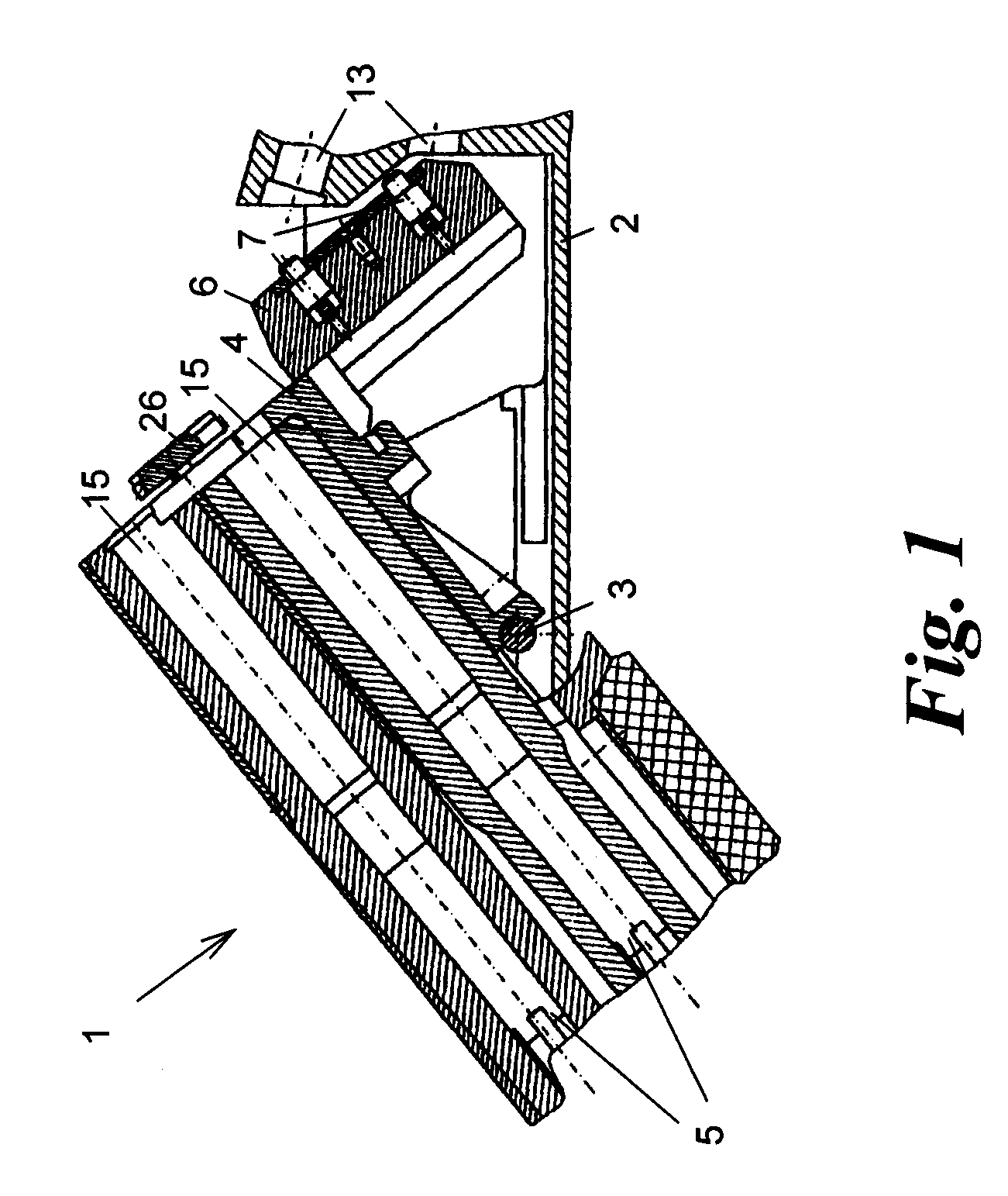
[0017]A drop-down (“tip-up”) barrel weapon 1 is shown in sections in FIG. 1, i.e. only in the region of its (here: open) block lock. The block lock comprises a link 2 and a mount 4 articulated thereto at 3 to accommodate two barrels 5 and a breech block 6, which is guided to be transversely displaceable on the mount 4, as is known in the art.

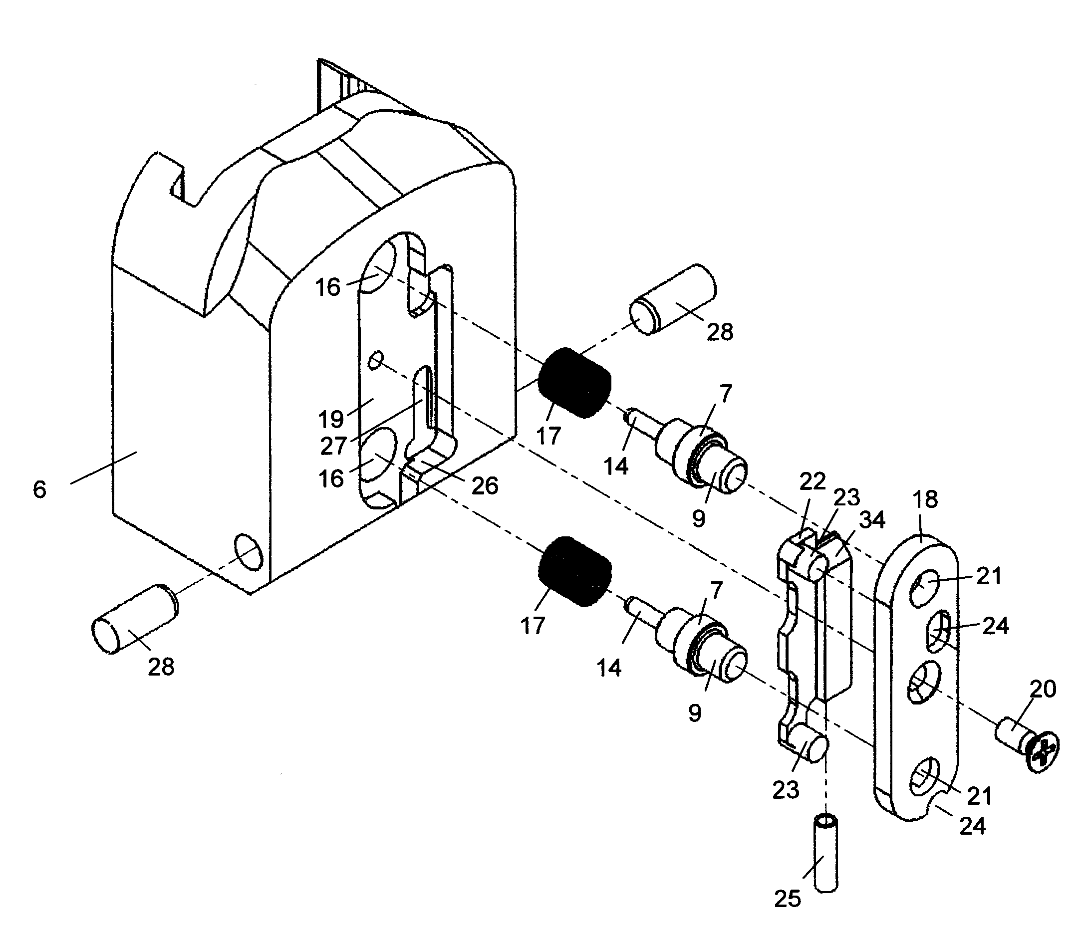
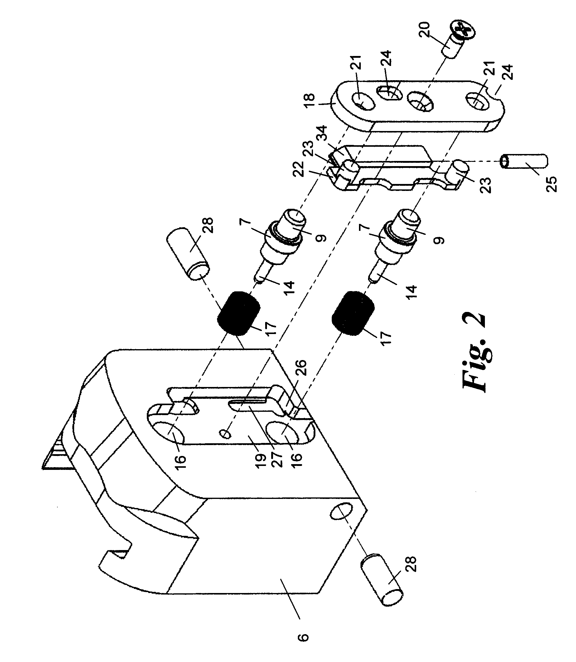
[0018]FIG. 2 shows the breech block 6 in detail. The breech block 6 contains two firing pins 7 guided displaceably in axial direction. Each firing pin 7 has an impact head 9 on its rear side for one respective firing piece 11 (FIGS. 3 and 4), which is guided in guides 13 (FIG. 1) of the link 2 and is biased for firing, as is known to the person skilled in the art. On its front side each firing pin 7 has a firing tip 14 for firing a cartridge (not shown) in the cartridge storage areas 15 of the barrels 5.

[0019]The firing pins 7 are guided in stepped holes 16 of the breech block 6 and respectively biased towards the firing pieces 11 by a pressure ...


PUM


Abstract

Breech block for a drop-down barrel weapon, having at least one firing pin, which is guided such that it can move axially therein, has an impact head at its rear end for a firing piece to strike, and has a firing tip at its front end in order to fire a cartridge, with a safety slide being guided such that it can move laterally in a recess on the firing piece side of the breech block between a first position in which a portion thereof in the form of a spacer head projects beyond the impact head of the firing pin in the impact area of the firing piece and a second position in which it is withdrawn from the impact area of the firing piece, which recess is at least partially closed by a cover plate with the cover plate having recesses for the impact head and the spacer head to pass through.

Description

[0001]This application is the U.S. National Phase of International Application No. PCT / AT2007 / 000018 filed on Jan. 18, 2007, the disclosure of which is incorporated herein by reference.BACKGROUND OF THE INVENTION[0002]The present invention relates to a breech block for a drop-down barrel weapon with at least one firing pin, which is guided to be axially displaceable therein and which has an impact head at its rear end for a firing piece to strike against and a firing tip at its front end for firing a cartridge, and also a block lock with such a breech block.[0003]A breech block of this type is known from patent EP 0 855 569 or EP 0 862 038, for example.[0004]Numerous systems are already known to secure block locks against unintentional release such as, for example, catch hooks for the firing pieces, holding devices for the tension springs etc., which are disengaged to release the safety mechanism of the weapon.[0005]Thus, patent DE 94 620 C, for example, discloses two levers, which ...

Claims


Application Information

Patent Timeline
IPC IPC(8): F41A3/58F41A19/27F41A17/64
CPCF41A17/70F41A3/58
Inventor KEFER, HUBERT
Owner STEYR MANNLICHER
Why Eureka
Try Eureka