
Fuel cell system

a fuel cell and system technology, applied in the field of fuel cell systems, can solve the problems of unnecessarily lowering the temperature of air supplied to the fuel cell, and difficulty in generating electricity

Active Publication Date: 2010-02-11
NISSAN MOTOR CO LTD
View PDF8 Cites 10 Cited by
  • Summary
  • Abstract
  • Description
  • Claims
  • Application Information

AI Technical Summary

Benefits of technology

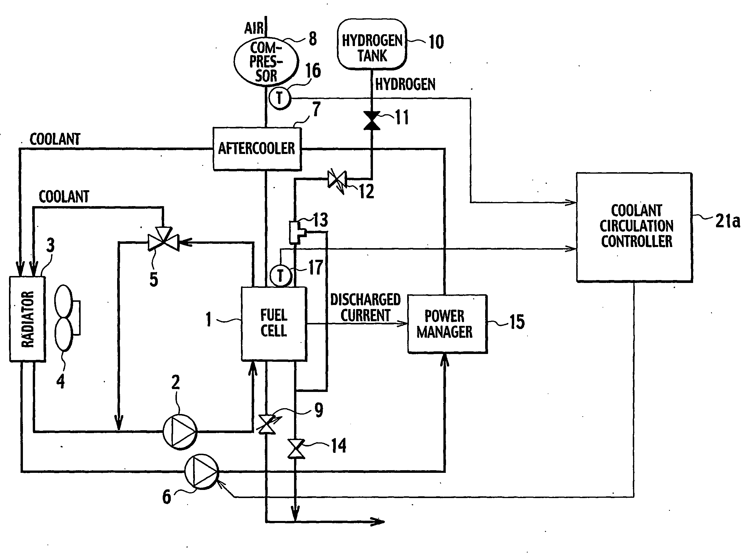
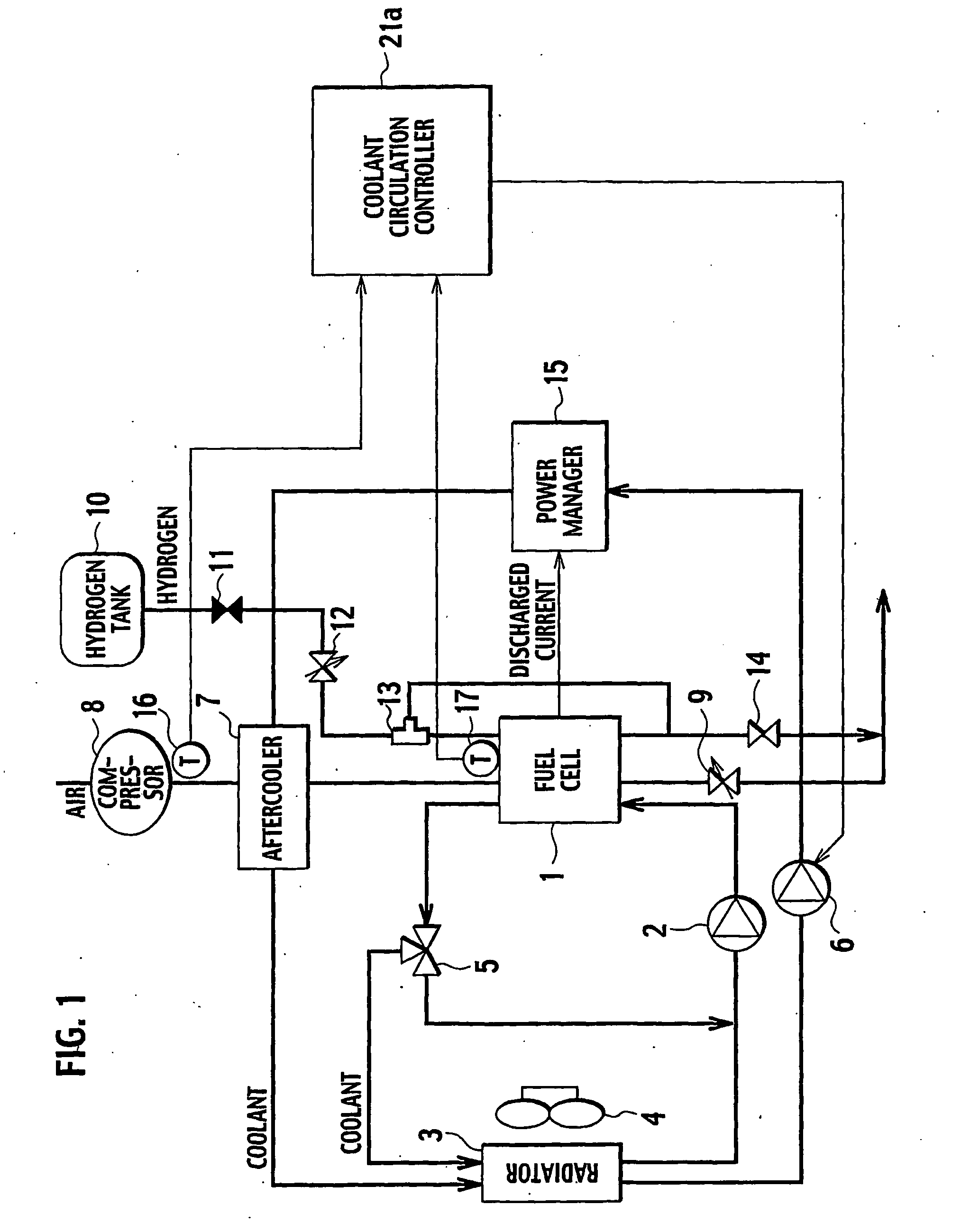
[0004]The present invention was made to solve such a conventional problem, and an object of the present invention is to provide a fuel cell system which enables the fuel cell to generate electricity at cold start-up by controlling circulation timing and flow rate of the coolant of the aftercooler such that the supplied air does not become cold.

Problems solved by technology

However, in the control method disclosed in the aforementioned document, when a coolant circulating through an air aftercooler is cold at cold start-up, heat exchange is performed between compressed air and the cold coolant in the air aftercooler, and the temperature of air supplied to the fuel cell is unnecessarily lowered.
Water of an electrolyte membrane is therefore frozen due to the cooled compressed air, thus causing a problem of making it difficult to generate electricity.

Method used


Image

  • Fuel cell system
  • Fuel cell system
  • Fuel cell system

Examples


first embodiment

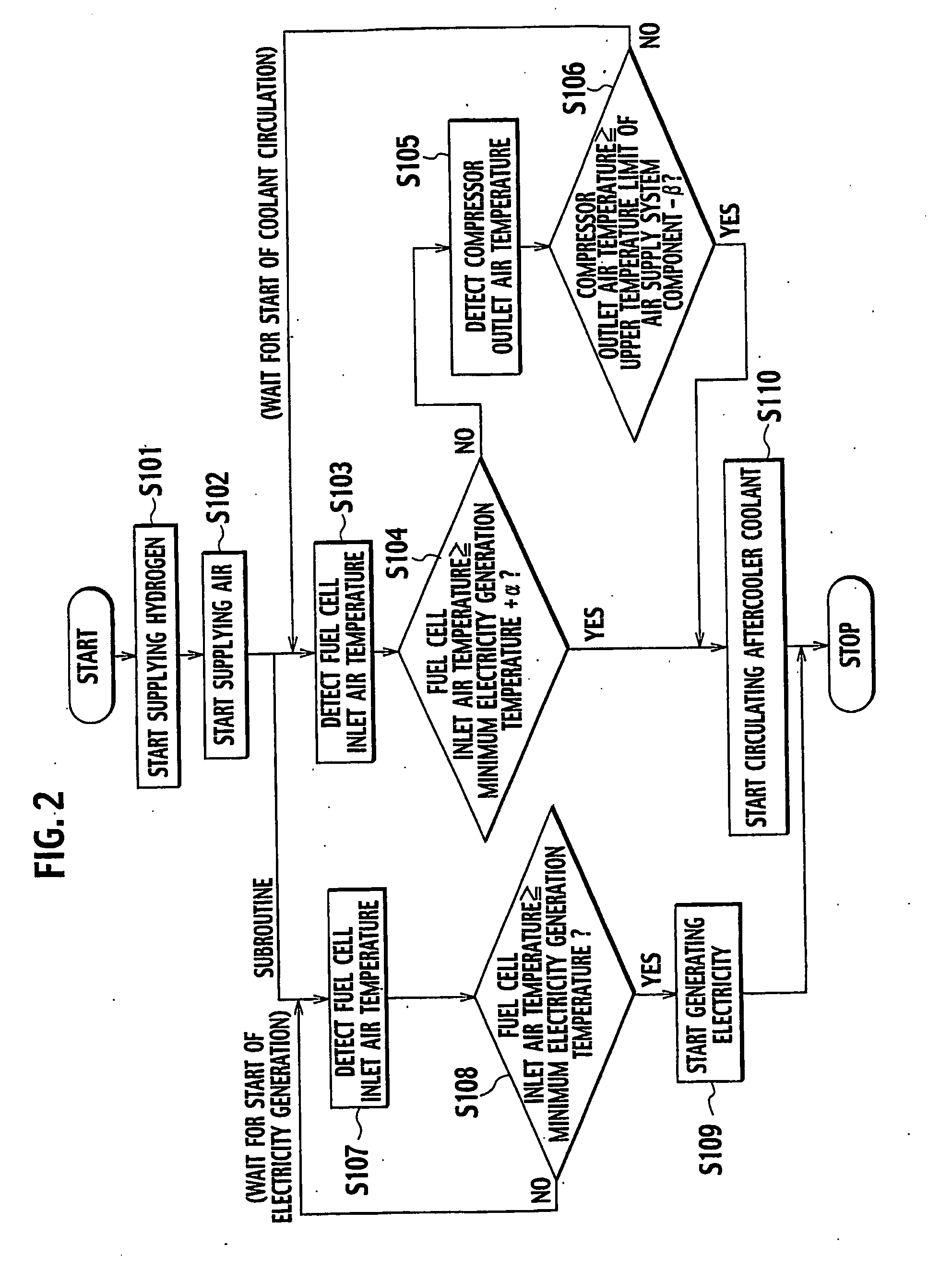
[0026]FIG. 1 shows a configuration of a fuel cell system according to a first embodiment of the present invention. The fuel cell system of the embodiment includes a fuel cell 1 and a power manager (PM) 15. The fuel cell 1 is supplied with hydrogen and air to generate electricity. The power manager 15 takes out and manages electric power generated by the fuel cell 1. The fuel cell system includes, as a hydrogen supply system, a hydrogen tank 10, a pressure reducing valve 11, a hydrogen pressure control valve 12, an ejector 13, and a purge valve 14 and includes, as an air supply system, a compressor 8, an aftercooler 7, and an air pressure control valve 9. As a cooling system for the fuel cell 1, the fuel cell system includes a pump 2, a radiator 3, a radiator fan 4, and a three way valve 5, and as a cooling system for the power manager 15, includes the radiator 3, the radiator fan 4, a pump 6, and the aftercooler 7. Furthermore, the fuel cell system includes, as a coolant circulation...

second embodiment

[0045]Next, a description is given of a fuel cell system according to a second embodiment. FIG. 4 shows a configuration of the fuel cell system according to the second embodiment. The fuel cell system of this embodiment, similar to the first embodiment, includes the fuel cell 1 and the power manager 15. Moreover, the hydrogen supply system, the air supply system, and the cooling systems for the fuel cell 1 and the power manager 15 have configurations equivalent to those of the first embodiment. The description of these components is therefore omitted. The configuration of this embodiment differs from that of the first embodiment in that an aftercooler inlet temperature sensor 18 corresponding to a coolant temperature detector and a coolant circulation controller 21b are provided as the coolant circulation control system.

[0046]The aftercooler inlet temperature sensor 18 detects temperature of the coolant at the inlet of the aftercooler 7. The coolant circulation controller 21b determ...

third embodiment

[0058]Next, a description is given of a fuel cell system according to a third embodiment. FIG. 8 shows a configuration of the fuel cell system according to the third embodiment. The fuel cell system of this embodiment, similar to the first embodiment, includes the fuel cell 1 and the power manager 15. Moreover, the hydrogen supply system, the air supply system and the cooling systems for the fuel cell 1 and the power manager 15 have configurations equivalent to those of the first embodiment. The description of these components is therefore omitted. The configuration of this embodiment differs from that of the first embodiment in that the aftercooler inlet temperature sensor 18 corresponding to a coolant temperature detector, a power manager temperature sensor 19 corresponding to a component temperature detector, and a coolant circulation controller 21c are provided as the coolant circulation control system.

[0059]The aftercooler inlet temperature sensor 18 detects temperature of the ...


PUM

PropertyMeasurementUnit
temperatureaaaaaaaaaa
oxidizing gas temperatureaaaaaaaaaa
oxidizing gas temperature detectoraaaaaaaaaa

Abstract

A fuel cell system of the present invention includes: a fuel cell (1) supplied with fuel gas and oxidizing gas to generate electricity; a fuel gas supply unit supplying the fuel gas to the fuel cell (1); an oxidizing gas supply unit supplying the oxidizing gas to the fuel cell (1); an aftercooler (7) cooling the oxidizing gas supplied to the fuel cell (1) by heat exchange with a coolant; an oxidizing gas temperature detector (16, 17) detecting temperature of the oxidizing gas; and a coolant circulation controller (21a) starting circulation of the coolant when the detected temperature of the oxidizing gas exceeds a predetermined value. The predetermined value is set to a value of not higher than a minimum electricity generation temperature of the fuel cell (1), and a circulation timing and flow rate of the coolant for the aftercooler (7) are controlled such that the supplied oxidizing gas does not become cold. This enables the fuel cell (1) to generate electricity at cold start-up.

Description

TECHNICAL FIELD[0001]The present invention relates to a fuel cell system including a fuel cell supplied with fuel gas such as hydrogen and oxidizing gas such as air to generate electricity, in which cold start control of the fuel cell is improved.BACKGROUND ART[0002]A conventional technology of a cold start control method of a fuel cell in a fuel cell system is disclosed in the Japanese Patent Laid-open Publication No. 2003-208914. In this fuel cell system, air is pressurized by a compressor at cold start-up to increase in temperature. Temperature of air supplied to the fuel cell is therefore increased to promote electricity generation.DISCLOSURE OF INVENTION[0003]However, in the control method disclosed in the aforementioned document, when a coolant circulating through an air aftercooler is cold at cold start-up, heat exchange is performed between compressed air and the cold coolant in the air aftercooler, and the temperature of air supplied to the fuel cell is unnecessarily lowere...

Claims


Application Information

Patent Timeline
Patent Type & Authority Applications(United States)
IPC IPC(8): H01M8/00H01M8/04
CPCH01M8/04007H01M8/04365H01M8/04328H01M8/04358H01M8/04373H01M8/04701H01M8/04708H01M8/04723H01M8/04731H01M8/04738H01M8/04768Y02E60/50H01M8/04067H01M8/04074H01M8/04223H01M8/04225
Inventor TANIGUCHI, IKUHIROSAKAI, HIROMASAAKASHI, KOTAROTAKAHASHI, NOBUTAKA
Owner NISSAN MOTOR CO LTD
Learn More