
Remote Diagnostics for Electronic Whiteboard

a technology of electronic whiteboards and remote diagnostics, applied in the field of electronic whiteboards, can solve the problems of insufficient tracking of pen/stylus tip tracking, inaccurate alignment, and inability to accurately replicate the whiteboard surface intended to alter the image of whiteboards

Active Publication Date: 2010-02-04
STEELCASE INC
View PDF10 Cites 12 Cited by
  • Summary
  • Abstract
  • Description
  • Claims
  • Application Information

AI Technical Summary

Benefits of technology

The patent describes a system for remotely diagnosing malfunctions of electronic whiteboards. The system includes a whiteboard surface, a position sensor, and a local computer that runs board software. A remote computer with a display links to the whiteboard and allows the remote technician to interact with the whiteboard surface and generate X and Y coordinates. These coordinates are then transmitted to the remote computer for display and analysis. The system can identify the cause of malfunctions and suggest ways to fix them. The technical effects of the system include improved diagnostics and repair of whiteboards in real-time, as well as the ability to identify and troubleshoot malfunctions remotely.

Problems solved by technology

While this solution works well when performed properly, when this solution is not performed properly or is performed in a sloppy fashion (e.g., the points selected by the user are not precisely aligned with the projected reference points), alignment is inaccurate and activities on the whiteboard surface intended to alter whiteboard images are imprecisely replicated by the whiteboard.
For instance, several different occurrences can degrade or substantially hinder pen / stylus tip tracking including lose or corruption of calibration data (e.g., due tot a power surge), sensor malfunctions, a short in between layered whiteboard sensors (e.g., due to debris lodged between layers), whiteboard power fluctuations, etc.
For example, whiteboard LEDs that indicate specific activities can burn out or otherwise be rendered unable to be illuminated.
As another example, a whiteboard cooling fan can malfunction.
As still one other instance, a whiteboard can malfunction when the laptop or PC used to control the whiteboard has application programs loaded thereon that are incompatible with the whiteboard application programs.
Thus, for instance, where a laptop has thirty different applications programs loaded in addition to the whiteboard application program, it may be that two of the application programs in addition to the whiteboard application program are not compatible with the whiteboard program so that the whiteboard program malfunctions in some respects during whiteboard activities.
In many cases symptoms of whiteboard malfunction may result from any of several different causes and in these cases it is often difficult to determine what a symptom is indicating.
For instance, where a whiteboard does not accurately track the tip of a stylus, is the inaccurate tracking symptom caused by loss or degradation of calibration data, a malfunctioning sensor, a malfunctioning board processor, a power malfunction, etc.
First, technicians are often highly trained people and therefore their time is very expensive.
Second, qualified technicians are not always immediately available for dispatch to malfunctioning boards and therefore there is often a delay between the time a request for technical support is lodged and the time at which a technician arrives at a board location to diagnose the cause of a malfunction.
This board down time is, at a minimum, a nuisance and in many cases can affects productivity of people that use the board.
While this solution works well in the case of PCs and laptops where software programs are to be examined for faulty operation, this solution does not work well in the case of a whiteboard where, when the board malfunctions, mirroring of the board image alone would be no more instructive as to the cause of the malfunction than if the technician were at the board location observing the board itself.

Method used


Image

  • Remote Diagnostics for Electronic Whiteboard
  • Remote Diagnostics for Electronic Whiteboard
  • Remote Diagnostics for Electronic Whiteboard

Examples


Embodiment Construction

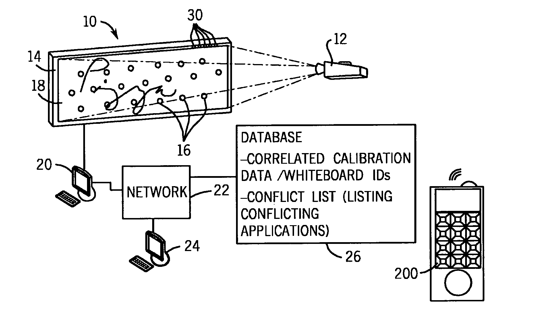
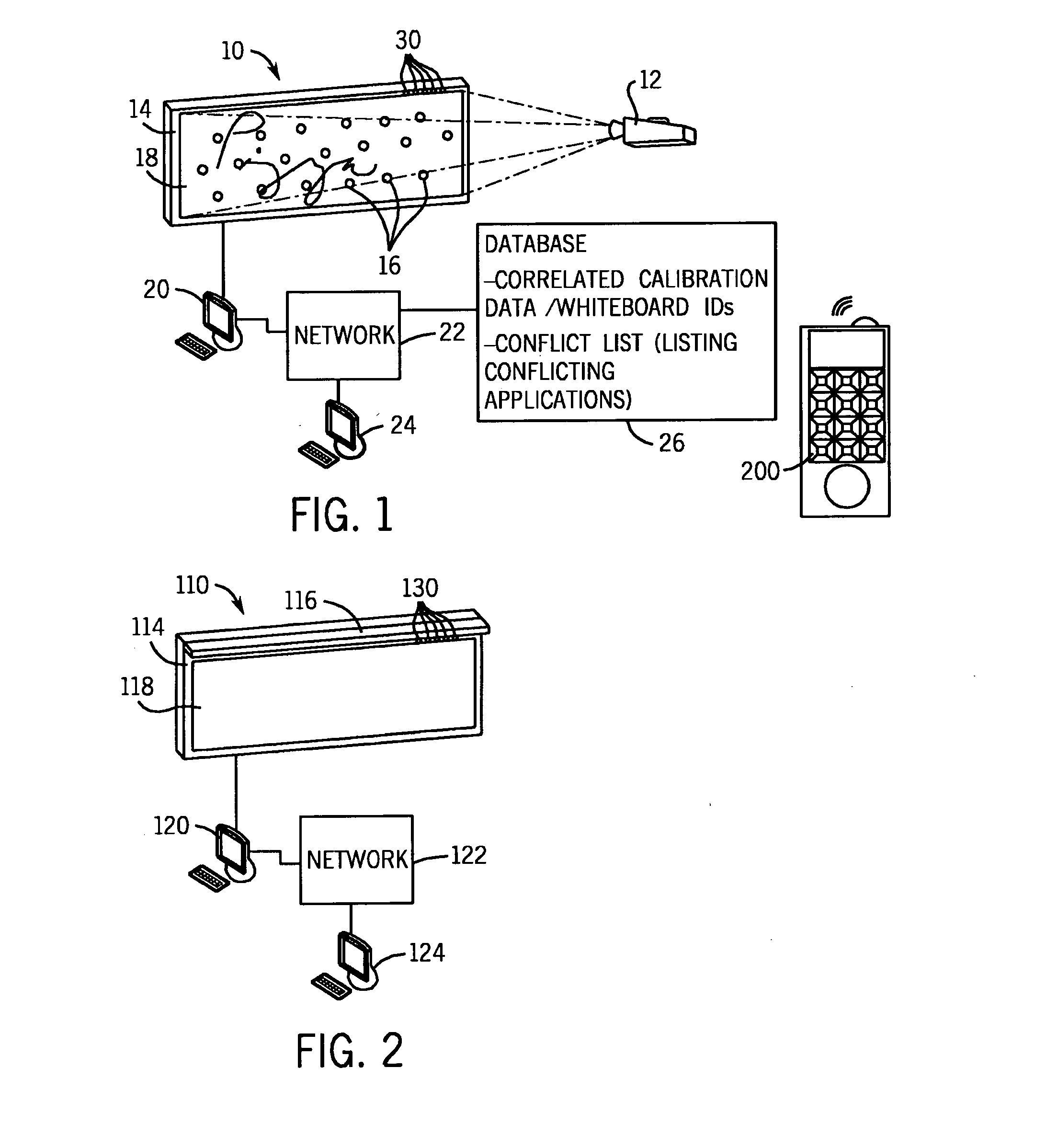
[0062]Referring to the figures wherein like reference numbers correspond to similar elements throughout the several views and more specifically, referring to FIG. 1, the present invention will be described in the context of an exemplary whiteboard system 10 that includes a projector 12, a whiteboard 14, a local computer 20 (e.g., a laptop or PC), a remote computer 24, a database 26 and a network 22 (e.g., the Internet, a local area network (LAN), etc.). The local computer 20 is linked to each of the whiteboard 14 and the projector 12 to control information projected onto the whiteboard and to obtain information from the whiteboard 14 associated with activities that occur on the board to change information displayed thereon. Referring also to FIG. 23, local computer 20 includes a processor 300, a display 302 and a memory 304. Local computer 20 stores programs in memory 304 and runs whiteboard application programs as well as a video driver program for driving projector 12. In addition...


PUM


Abstract

A method and apparatus for diagnosing causes of a malfunction of an electronic whiteboard that includes a white-board surface, a position sensor for sensing surface activity and generating at least one of X and Y coordinates associated with the surface activity and a local computer that runs board software to convert the at least one of X and Y coordinates into operational commands, the method comprising the steps of linking a remote computer that includes a remote display to the electronic whiteboard from a remote location, interacting with the whiteboard surface to generate X and Y coordinates associated with surface activity, transmitting at least one of the X and Y coordinates associated with the surface activity to the remote computer, displaying at least a subset of the at least one of X and Y coordinates via the remote display and examining the at least a subset of the at least one of X and Y coordinates via the remote display to ascertain the cause of a board malfunction.

Description

CROSS-REFERENCE TO RELATED APPLICATIONS[0001]This application claims benefit of U.S. Provisional Patent Application No. 60 / 811,346 filed Jun. 6, 2006.STATEMENT REGARDING FEDERALLY SPONSORED RESEARCH OR DEVELOPMENT[0002]Not applicable.BACKGROUND OF THE INVENTION[0003]The present invention relates to electronic whiteboards and more specifically to remote diagnostic systems for electronic whiteboards.[0004]Various types of electronic whiteboards have been developed to help people share information. To this end, most electronic whiteboards include a large flat surface on which information is applied for viewing by people within a conference or other type of space, some type of a sensor system for sensing interactive activities with the whiteboard surface that are intended to alter the information presented on the surface, some type of whiteboard driver for controlling the information that is present on the whiteboard surface and a computer (e.g., a laptop, PC, etc.) to run whiteboard an...

Claims


Application Information

Patent Timeline
Patent Type & Authority Applications(United States)
IPC IPC(8): G06F19/00G06F15/00
CPCG05B23/0256
Inventor KVAVLE, BRAND C.WATSON, JAMES D.HOFMANN, NEAL A.BEHNER, DAVID W.ASHFORD, LOUIS A.
Owner STEELCASE INC
Learn More