
Multimode Optical Fibers

a multi-mode optical fiber and optical fiber technology, applied in the field of optical fiber transmission, can solve the problems of deterioration of signal modulation, difficult control of exact parameter value , more complex and expensive optical systems

Active Publication Date: 2010-02-04
DRAKA COMTEQ BV
View PDF99 Cites 152 Cited by
  • Summary
  • Abstract
  • Description
  • Claims
  • Application Information

AI Technical Summary

Benefits of technology

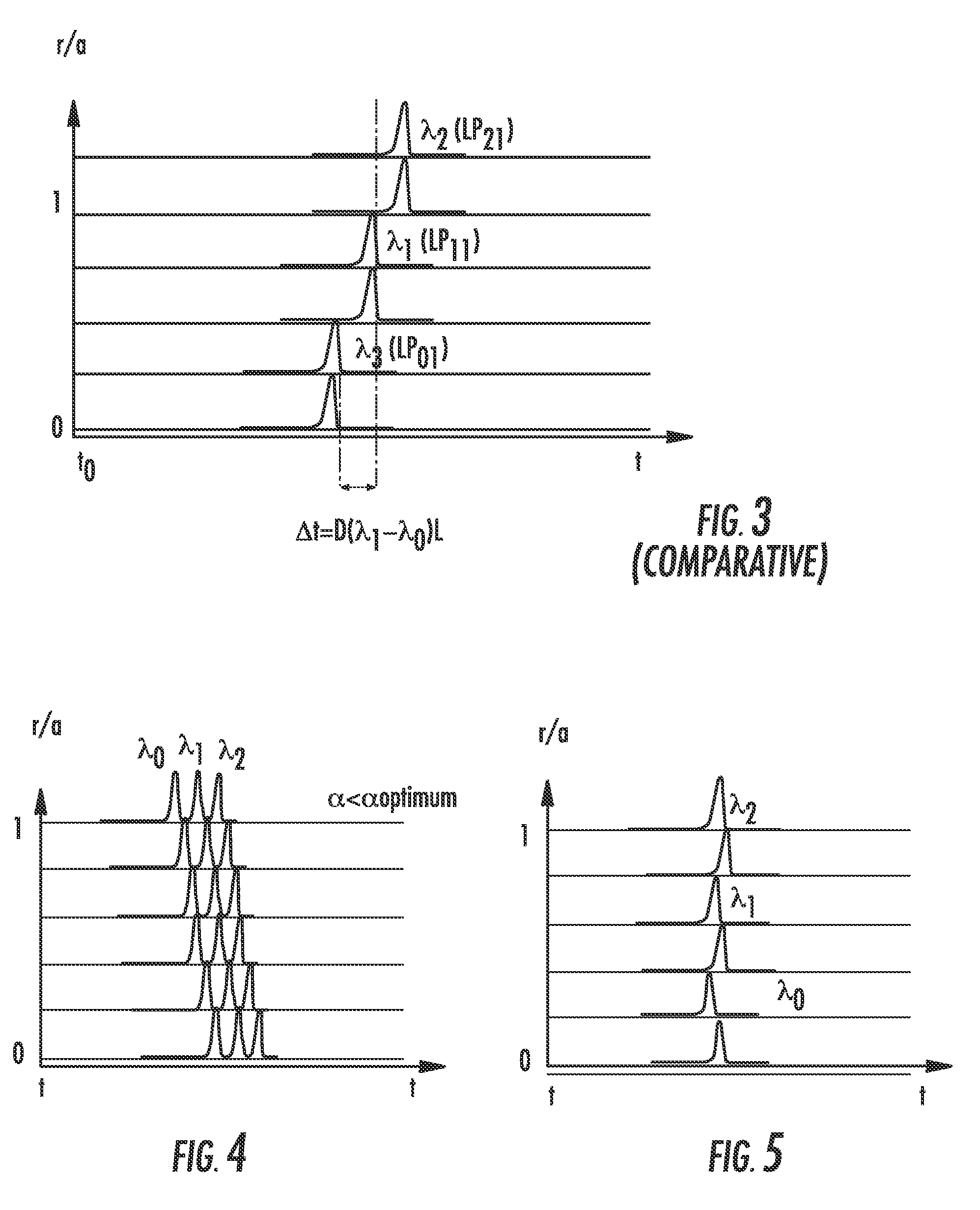
The invention proposes to use the chromatic dispersion of a multimode optical fiber to compensate for the modal dispersion induced by a polychromatic signal. By adjusting the profile of the fiber and introducing a modal dispersion that will compensate within the fiber, the invention proposes to use the chromatic dispersion of the fiber to introduce a modal dispersion that will compensate for the chromatic dispersion when a transverse polychromatic and multimode source is used. The invention also proposes a method for selecting multimode optical fibers based on their dispersion modal delay. The technical effect of the invention is to improve the performance of optical systems that use polychromatic sources by compensating for the modal dispersion and reducing the impact of chromatic dispersion.

Problems solved by technology

Furthermore, the exact parameter value α is difficult to control during fiber manufacturing.
Using fiber concatenations for modal dispersion compensation leads to more complex and more costly optical systems.
However, such a conditioning of the signal at the input of the multimode fiber involves a significant degradation of the signal modulation and consequently an increase in the bit error rate (BER).
U.S. Patent Publication No. 2005 / 0078962, which is hereby incorporated by reference in its entirety, proposes to offset the VCSEL output from the center of the multimode fiber in order to introduce the signal into a “large bandwidth zone.” Such an offsetting, however, is difficult to control and has to be adjusted for each fiber.
Moreover, it may introduce a power loss, which is detrimental to the transmission quality.

Method used


Image

  • Multimode Optical Fibers
  • Multimode Optical Fibers
  • Multimode Optical Fibers

Examples


Embodiment Construction

[0059]In this regard, the invention proposes an optimized multimode optical fiber for use with a polychromatic source, such as a VCSEL laser, having several transverse modes.

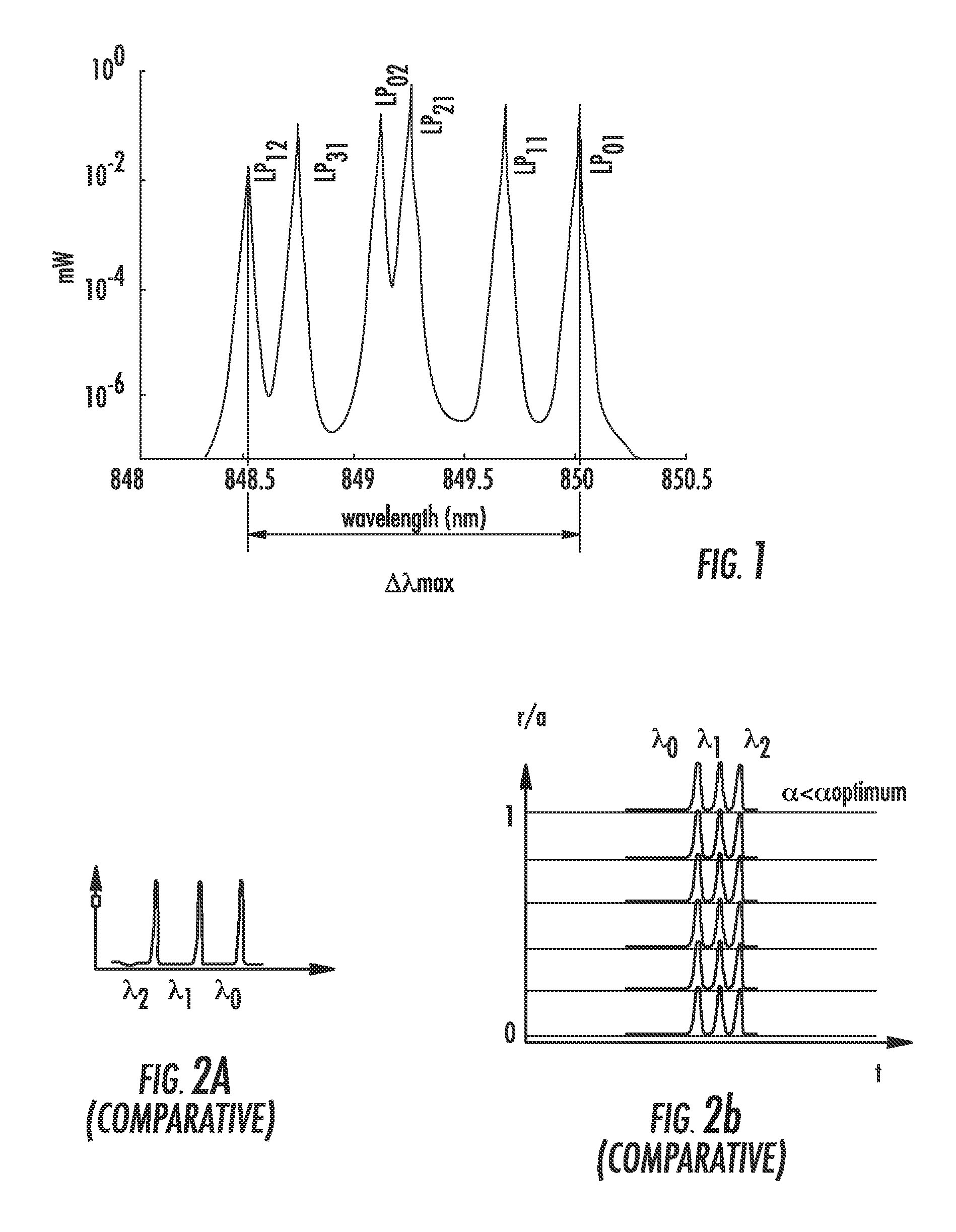
[0060]FIG. 1 shows an emission spectrum of a VCSEL laser, with a mode centered on 850 nanometers for the excitation of the fundamental mode LP01. FIG. 1 shows that each transverse mode of the laser has its own wavelength. The maximum RMS (Root Mean Square) spectral width generally authorized for high-speed transmission is 0.46 nanometers RMS for the VCSEL (as defined in the standard IEEE 802.3ae).

[0061]In this regard, when the optical signal emitted by the VCSEL is introduced into the multimode fiber, each transverse mode of the VCSEL diffracts differently. The transverse modes of the highest order diverge more rapidly (i.e., due to their phase and spatial distribution of their energy), and will therefore be coupled more specifically in the high order modes of the fiber. Those having ordinary skill in the art wi...


PUM


Abstract

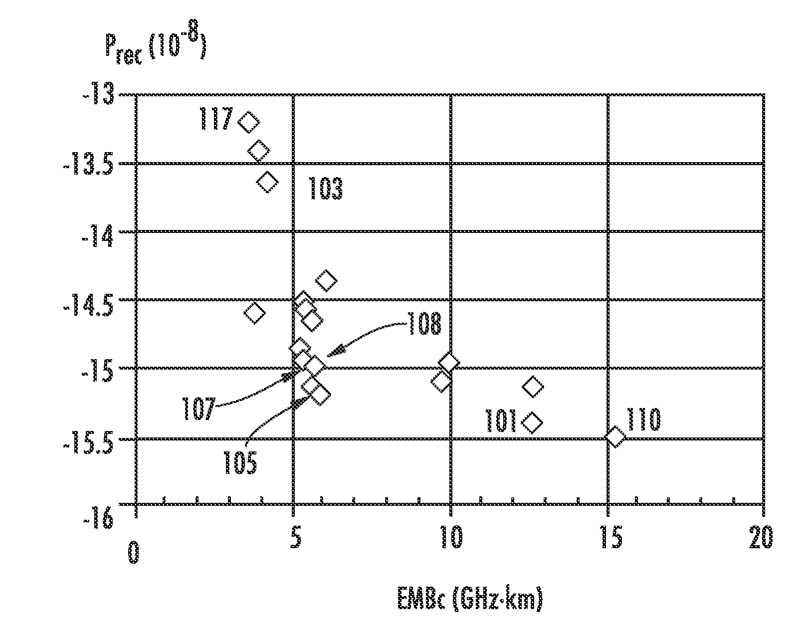
A multimode optical fiber has an equivalent modal dispersion value (DMDinner&outer) of less than 0.11 ps / m for (Δλmax×D)>0.07 ps / m as measured on a modified DMD graph. The modified DMD graph accounts for chromatic dispersion to ensure that the multimode optical fiber has a calculated effective bandwidth EBc greater than 6000 MHz-km when used with multimode transverse sources.

Description

CROSS-REFERENCE TO PRIORITY APPLICATION[0001]This application claims the benefit of pending French application Ser. No. 08 / 03873 for “Fibres Optiques Multimodes” (filed Jul. 8, 2008, at the French Patent Office), which is hereby incorporated by reference in its entirety.FIELD OF THE INVENTION[0002]The present invention relates to the field of optical fiber transmissions, and more specifically, to multimode fibers used for short-distance optical transmission systems that require large bandwidth.BACKGROUND OF THE INVENTION[0003]Multimode optical fibers are used for short-distance applications and local networks. The core of a multimode fiber generally has a diameter of approximately 50 microns (μm) and a numerical aperture greater than 0.2. By way of comparison, a single-mode fiber generally has a diameter of approximately 8 to 9 microns (μm) and a numerical aperture greater than 0.12. Thus, for a particular wavelength, several optical modes propagate simultaneously along the fiber, c...

Claims


Application Information

Patent Timeline
Patent Type & Authority Applications(United States)
IPC IPC(8): H04B10/00G02B6/26H04B10/2581
CPCG02B6/0288G02B6/02214G01M11/338
Inventor GHOLAMI, ASGHARMOLIN, DENISSILLARD, PIERRELUMINEAU, YVES
Owner DRAKA COMTEQ BV
Learn More