
Display device, display method, and electronic device

a display device and display method technology, applied in the field of display devices, display methods, electronic devices, can solve the problems of increasing the weight of such circuits and the like, increasing the cost of such feedback systems, and further miniaturization and light weight may not be desired, so as to achieve the elimination of the feedback system for light emitting control and improve image quality

Active Publication Date: 2010-01-28
JAPAN DISPLAY WEST
View PDF2 Cites 15 Cited by
  • Summary
  • Abstract
  • Description
  • Claims
  • Application Information

AI Technical Summary

Benefits of technology

[0008]A display device of the related art (hereinafter sometimes simply referred to as “display device of related art”) applied with the technique of the related art that further simplifies the feedback for the light emission control in the non-light emitting display device having a separate light source (hereinafter sometimes simply referred to as “non-light emitting display device”) only includes a feedback loop of one system. Thus, in the display device of the related art, the cost necessary for the feedback loop can be further saved. However, since the display device of the related art still requires the feedback system for the light emission control, increase in cost due to the arrangement of such feedback system is inevitable.
[0011]The present invention addresses the above-identified, and other issues associated with conventional methods and apparatuses, and it is desirable to provide a new and improved display device that eliminates the feedback system for light emission control in the non-light emitting display device having a separate light source and that achieves higher image quality, a display method, and an electronic device.
[0013]According to such configuration, elimination of the feedback system for light emitting control and higher image quality are achieved in the non-light emitting display device having a separate light source.
[0018]Through the use of such method, elimination of the feedback system for light emitting control and higher image quality are achieved in the non-light emitting display device having a separate light source.
[0020]According to such configuration, elimination of the feedback system for light emitting control and higher image quality are achieved in the non-light emitting display device having a separate light source.
[0021]According to the embodiments of the present invention described above, elimination of the feedback system for light emitting control and higher image quality are achieved in the non-light emitting display device having a separate light source.

Problems solved by technology

However, since the display device of the related art still requires the feedback system for the light emission control, increase in cost due to the arrangement of such feedback system is inevitable.
That is, in the display device of the related art, a space for installing the circuits and the like that configure the feedback system is necessary, and increase in weight due to such circuits and the like is inevitable.
Therefore, if the display device of the related art is applied to the portable device such as the above, further miniaturization and lighter weight may not be desired.
Furthermore, the technique of the related art that further simplifies the feedback for light emission control in the non-light emitting display device merely achieves simplification of the feedback for light emission control and does not take into consideration higher image quality of the displayed image (still image / moving image).
Therefore, higher image quality of the displayed image (still image / moving image) is not expected in the display device of the related art applied with the technique of the related art.

Method used


Image

  • Display device, display method, and electronic device
  • Display device, display method, and electronic device
  • Display device, display method, and electronic device

Examples


Embodiment Construction

[0042]Hereafter, preferred embodiments of the present invention will be described in detail with reference to the appended drawings. Note that in this specification and the appended drawings, structural elements that have substantially the same functions and structures are denoted with the same reference numerals and a repeated explanation of these structural elements is omitted.

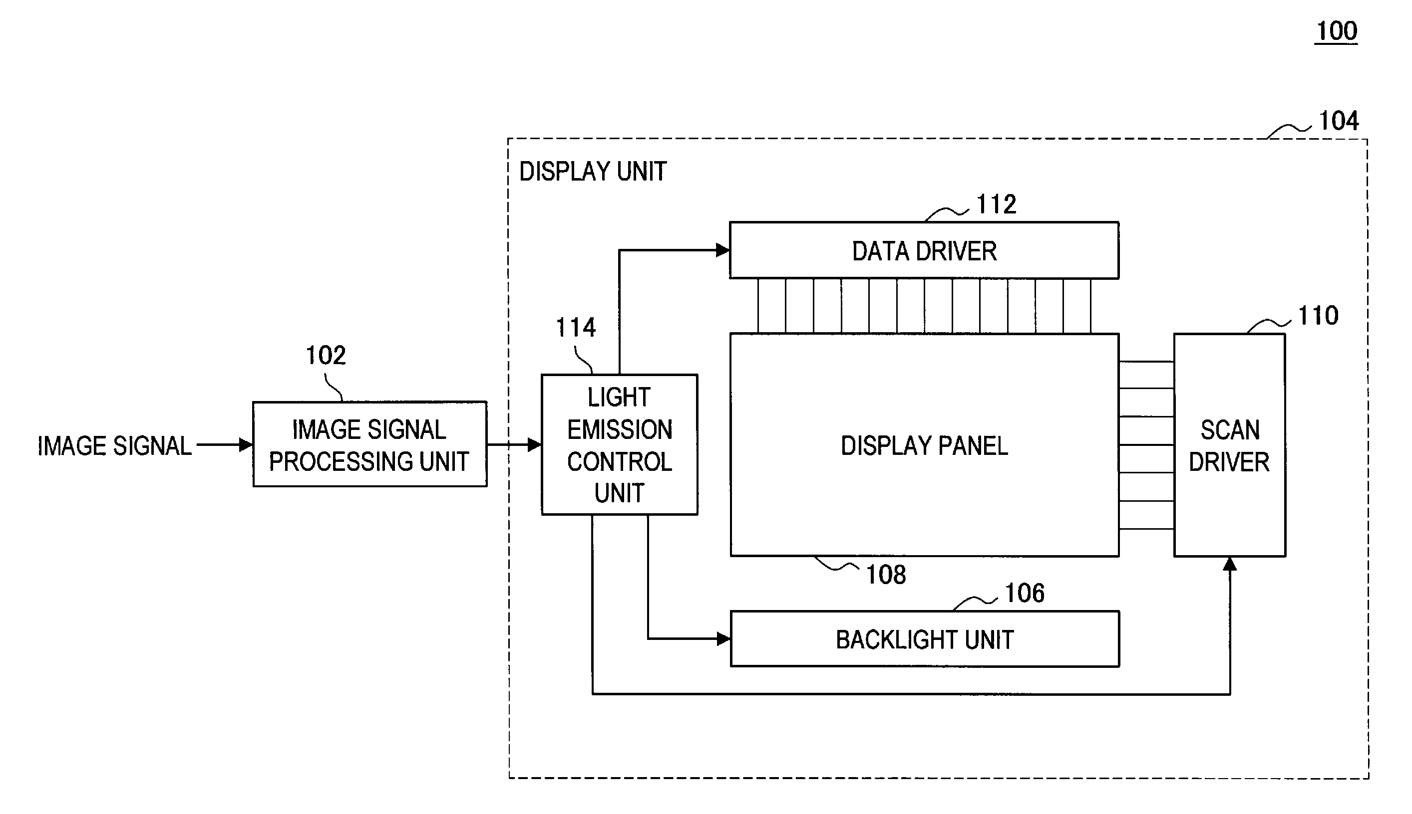
[0043]The liquid crystal display will be described below by way of example as the display device according to the embodiment of the present invention, but the display device according to the embodiment of the present invention is not limited thereto. For instance, the display device according to the embodiment of the present invention may be applied to a non-light emitting display device having a separate light source such as a DMD (Digital Micromirror Device). The description will be made below assuming that the display device according to the embodiment of the present invention displays the image correspon...


PUM


Abstract

There is provided a display device, including a display panel; a first light emitting unit for inputting a first input light to the display panel based on a first light emitting signal; a second light emitting unit for inputting second input light to the display panel based on a second light emitting signal; and light emitting control unit for outputting the first light emitting signal, the second light emitting signal, the image signal corresponding to the first input light, and the image signal corresponding to the second input light; where the light emitting control unit performs output of the first light emitting signal and the image signal of the color corresponding to the first input light in synchronization in a first sub-frame, and performs output of the second light emitting signal and the image signal of the color corresponding to the second input light in synchronization in a second sub-frame.

Description

BACKGROUND OF THE INVENTION[0001]1. Field of the Invention[0002]The present invention relates to a display device, a display method, and an electronic device.[0003]2. Description of the Related Art[0004]In recent years, various display devices such as organic EL display (Organic Electro Luminescence display; or also referred to as OLED display (Organic Light Emitting Diode display)), FED (Field Emission Display), LCD (Liquid Crystal Display), and PDP (Plasma Display Panel) are developed as a display device taking the place of a CRT display (Cathode Ray Tube display). Among such display devices, the liquid crystal display can be driven at low power consumption, and lower cost is advancing with maturity in production technique, and thus is being widespread used in an accelerating pace as a display device of the next generation taking the place of the CRT display.[0005]The liquid crystal display is a non-self emitting display device equipped with a liquid crystal panel with a liquid cr...

Claims


Application Information

Patent Timeline
IPC IPC(8): G09G3/36
CPCG02F1/133603G02F2001/133614G09G3/2025G09G2320/043G09G3/3648G09G2310/0235G09G3/3413G02F1/133614
Inventor YOU, EIHOKIMURA, SUSUMUSUZUKI, HIROMASAHIGUCHI, MASARU
Owner JAPAN DISPLAY WEST
Learn More