
Pcl retaining acl substituting tka apparatus and method

a technology of retaining acl and retaining acl, which is applied in the field of total knee arthroplasty (“ tka, apparatus and method of knee replacement surgery”), can solve the problems of significantly less success, significantly normal functional improvement in joint mobility, and knee replacement surgery, and achieves normal range of motion and function. , the effect of more functional

Active Publication Date: 2010-01-21
MASINI MICHAEL A
View PDF26 Cites 82 Cited by
  • Summary
  • Abstract
  • Description
  • Claims
  • Application Information

AI Technical Summary

Benefits of technology

[0008]Accordingly, it is an object of this invention to provide a knee replacement which is significantly more functional than currently existing devices allowing for more normal range of motion and function.
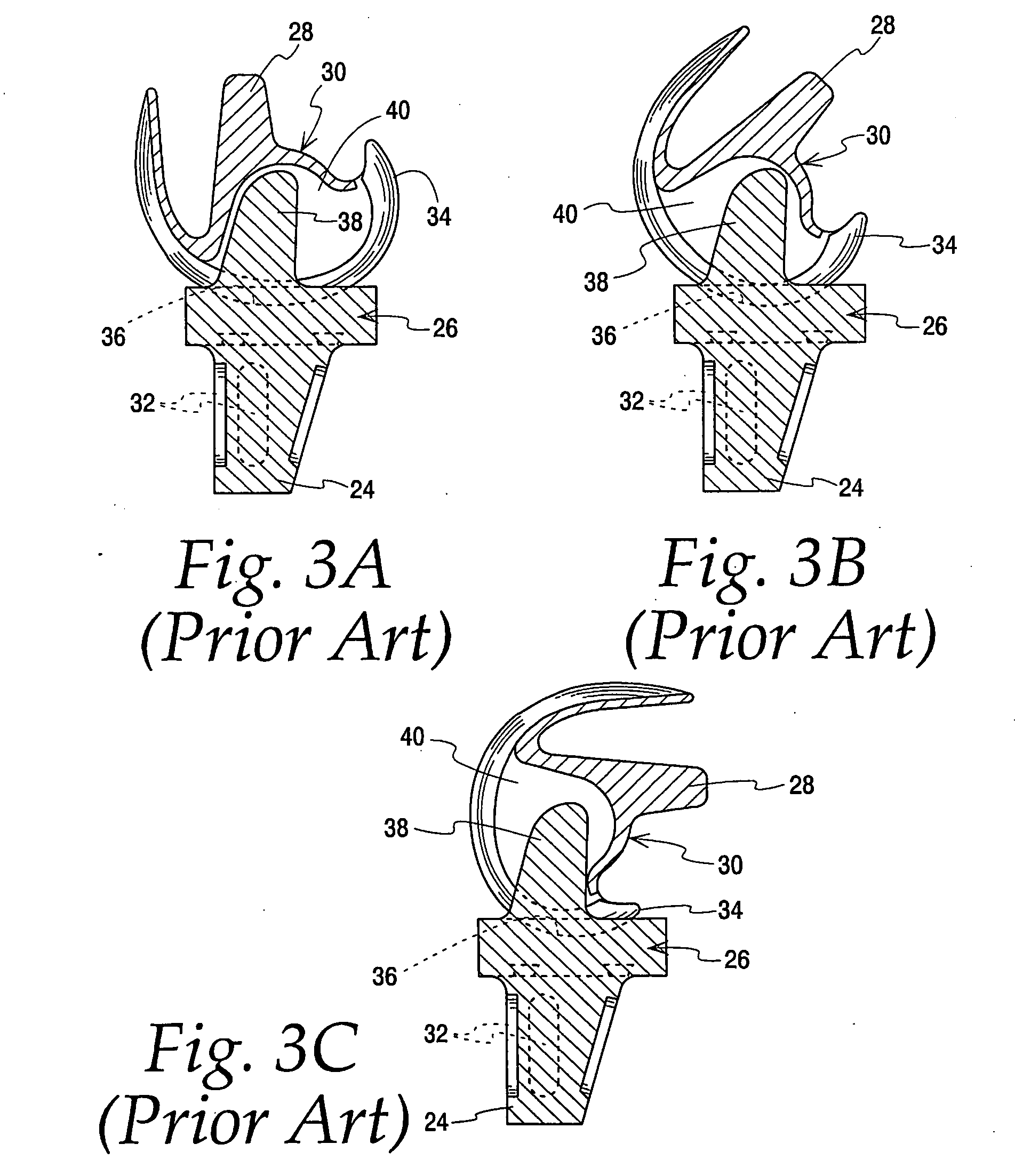
[0010]A more specific object of this invention is to use articular geometry and an anterior located CAM post type mechanism to provide a knee replacement whereby the function of the ACL will be substituted while still maintaining the PCL allowing it to perform its normal function including improved proprioception and roll back.
[0011]Another object of this invention is to provide a knee replacement which not only provides significant improvement relative to pain but also, and perhaps more importantly, improved function and mobility for high levels of activity including sports.

Problems solved by technology

Knee replacement surgery, though effective for pain, has traditionally been unable to result in significantly normal functional improvement in joint mobility.
These have been significantly less successful than resurfacing devices due to the increased constraint placed on the bone and thus most studies have shown a higher incidence of loosening.
Unfortunately, in all current devices and methods, the function of the ACL has been sacrificed or the balancing of the knee with retention of both ligaments has been difficult to achieve.
The result has been implants which generally function insufficiently for high levels of activity, especially sports, due to either a mismatch between the flexion and extension gaps due to excessive ligament tightening or loosening or irregular bone cuts and / or instability due to ligament deficiency.

Method used


Image

  • Pcl retaining acl substituting tka apparatus and method
  • Pcl retaining acl substituting tka apparatus and method
  • Pcl retaining acl substituting tka apparatus and method

Examples


Embodiment Construction

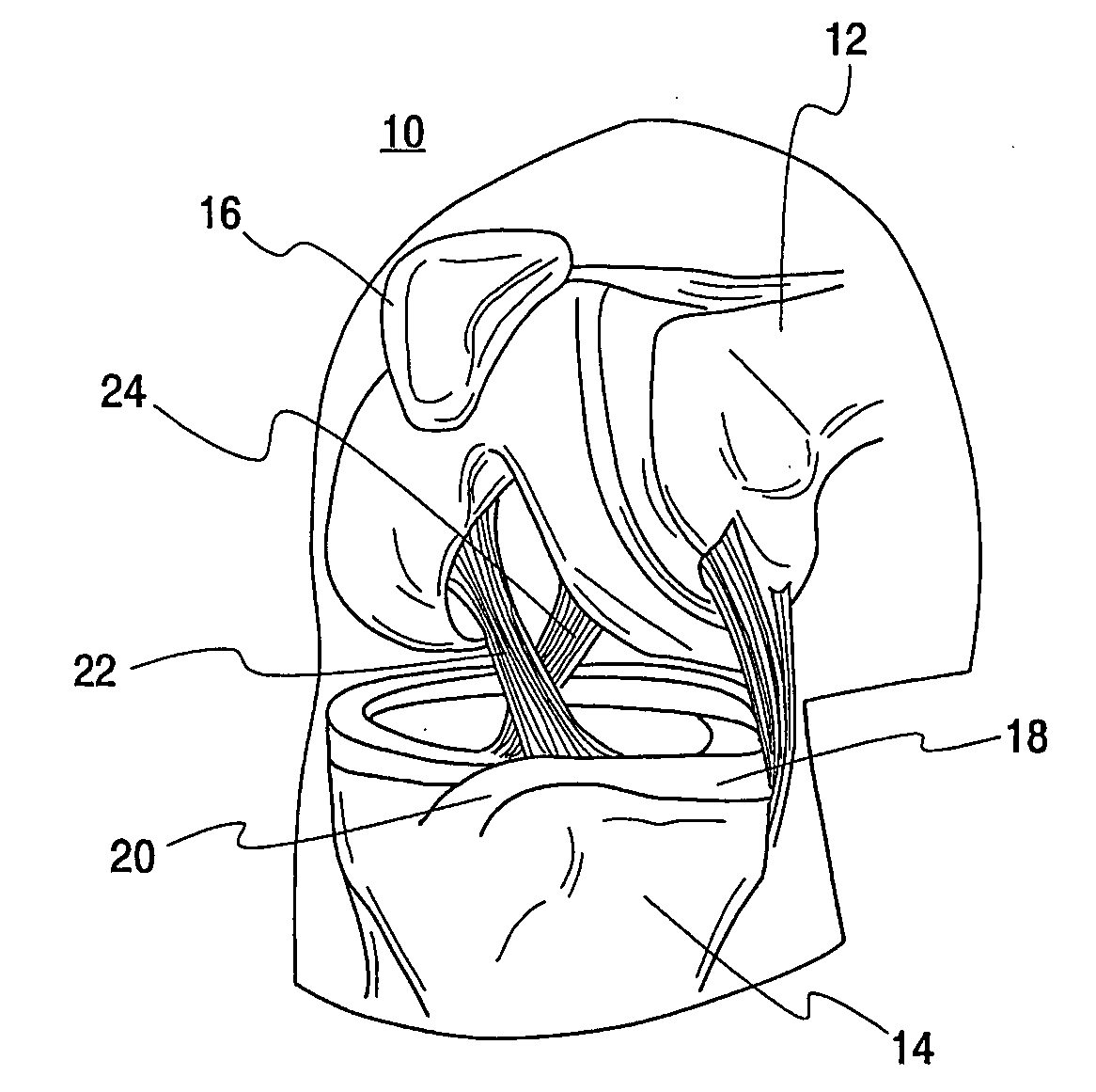
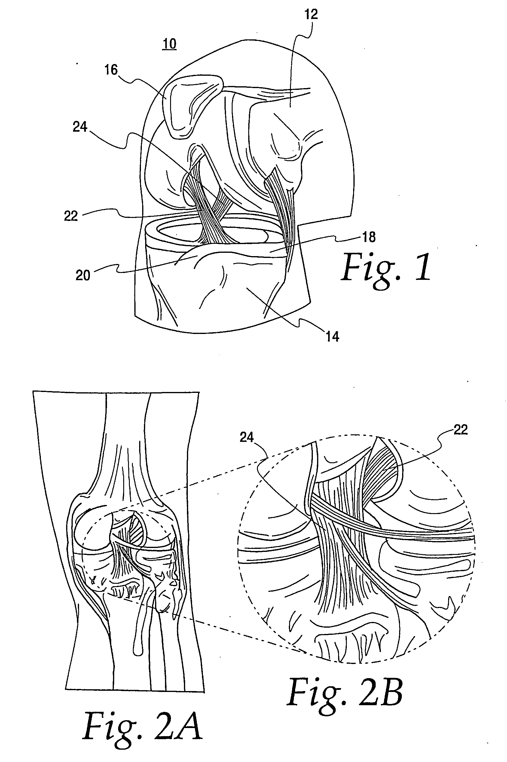
[0026]Turning now to the Figures, FIG. 1 is illustrative of a human knee joint 10. The knee is a lower extremity joint connecting the femur 12 and the tibia 14, with the patella 16 riding the joint as the knee bends. Between the bones of the femur 12 and tibia 14 is a structure made of cartilage, called the meniscus 18. The meniscus is a C-shaped piece of tissue attached to the tibia via the meniscal ligament 20 and helps to protect the joint and allows the bones to slide freely on each other. The bones themselves are coated with a different type of cartilage called hyaline cartilage which forms the joint surface on each bone respectively. There are two cruciate ligaments located in the center of the knee joint. The anterior cruciate ligament (ACL) 22 and the posterior cruciate ligament (PCL) 24 (see also FIGS. 2A and 2B) are the major stabilizing ligaments of the knee. The ACL 22 prevents the femur 12 from sliding backwards on the tibia 14 (or the tibia sliding forwards on the femu...


PUM


Abstract

A new class of total knee replacement includes a posterior cruciate ligament retaining anterior cruciate ligament substituting apparatus and method. Particular design considerations include: 1) a specific extension surface separate from the flexion surface, 2) rotational control in full extension to create the so-called screw-home mechanism, 3) translation restraints that will substitute for ACL function including a CAM-post or other abutment mechanism while allowing normal PCL function which should improve natural proprioception, 4) a modified femoral component with separate radii of curvature for the flexion and extension arcs of at least one condyle, and 5) a tibial component with slope built into the posterior aspect of its bone contacting surface on both sides of the PCL.

Description

FIELD OF THE INVENTION[0001]The present invention relates generally to arthroplasty and more particularly to total knee arthroplasty (“TKA”). More specifically, this invention relates to an apparatus and method of knee replacement surgery wherein the posterior cruciate ligament (“PCL”) is retained while the anterior cruciate ligament (“ACL”) is substituted for.DESCRIPTION OF THE PRIOR ART[0002]Knee replacement surgery, though effective for pain, has traditionally been unable to result in significantly normal functional improvement in joint mobility. In the history of total knee replacement, there is a long track record of providing improved pain relief for patients with advanced arthritic change of the knee. In these procedures, usually a femoral component is used to resurface the end of the distal femur and a tibial component is used to resurface the proximal portion of the tibial. Similarly, a patellar component may be used to resurface the patella. Basically, the ends of the bone...

Claims


Application Information

Patent Timeline
Patent Type & Authority Applications(United States)
IPC IPC(8): A61F2/38A61F2/08
CPCA61F2/385A61F2/3854A61F2/3868A61F2230/0006A61F2002/30116A61F2002/30616A61F2002/30688A61F2/3886
Inventor MASINI, MICHAEL A.
Owner MASINI MICHAEL A
Learn More