System for rotating a wind turbine blade

a technology of wind turbine blades and systems, which is applied in the direction of rotors, passive/reactive control, vessel construction, etc., can solve the problems of excessive blade stress, severe uncontrolled load, and the need for cam followers to operate valves, etc., and achieve the effect of less spa

Active Publication Date: 2010-01-21
GAMESA INNOVATION & TECH SA
View PDF9 Cites 17 Cited by
  • Summary
  • Abstract
  • Description
  • Claims
  • Application Information

AI Technical Summary

Benefits of technology

[0038]In another embodiment of the present invention, the hydraulic actuator is configured for blade pitch regulation also under normal operating condition of the wind turbine blade. Hereby is provided a technically less demanding system for blade pitch regulation. In this way, the pitch system requires less space, as the normal operating system and the emergency system can make use of the same hydraulic fluid lines. This fulfils an even further object of the present invention to provide a system and a method where the same mechanism is used to turn the blades during emergency stop as well as for normal operation.
[003

Problems solved by technology

This can be done in controlled manner in most cases, but during emergency stops, in case of grid drop out, failure in generator or control system, the pitching of the blades in order to achieve the emergency stop can introduce severe uncontrolled loading.
On the other hand, feathering at a constant, rapid rate may result in excessive blade stresses due to substantial decelerating torque and reverse thrust developed by the blades as they approach fully feathered positions.
One drawback of this invention is a cam follower is required to operate a valve.
The cam follower is expensive and troublesome to manufacture.
Another drawback of this invention is that it uses a separate actuator to turn the blades during emergency stop and another actuator for normal operation.
A further drawback of the disclosure is that the use of an electrically driven pump to turn the blades during emergency.
In the case of power failure, this may have fatal consequences.
The crucial problem is that the flow control valves are inexact.
This lack of accuracy involve that flow of 11 degree/sec. may occur.
Another drawback is that the pitch speed depends on the viscosity of the oil and hence the temperature of th

Method used


Image

  • System for rotating a wind turbine blade
  • System for rotating a wind turbine blade
  • System for rotating a wind turbine blade

Examples


Embodiment Construction

[0011]It is an object of the present invention to provide a simple and reliable system and method for controlling a wind turbine blade pitch during an emergency stopping process of a rotor in a wind turbine without the above mentioned disadvantages. Especially, it is the purpose of the invention to provide a method and system, in which the stopping process is reliable and simple and does function also during power failure.

[0012]Other advantages of the present invention and the specific embodiments thereof will become apparent in the following disclosure of the invention.

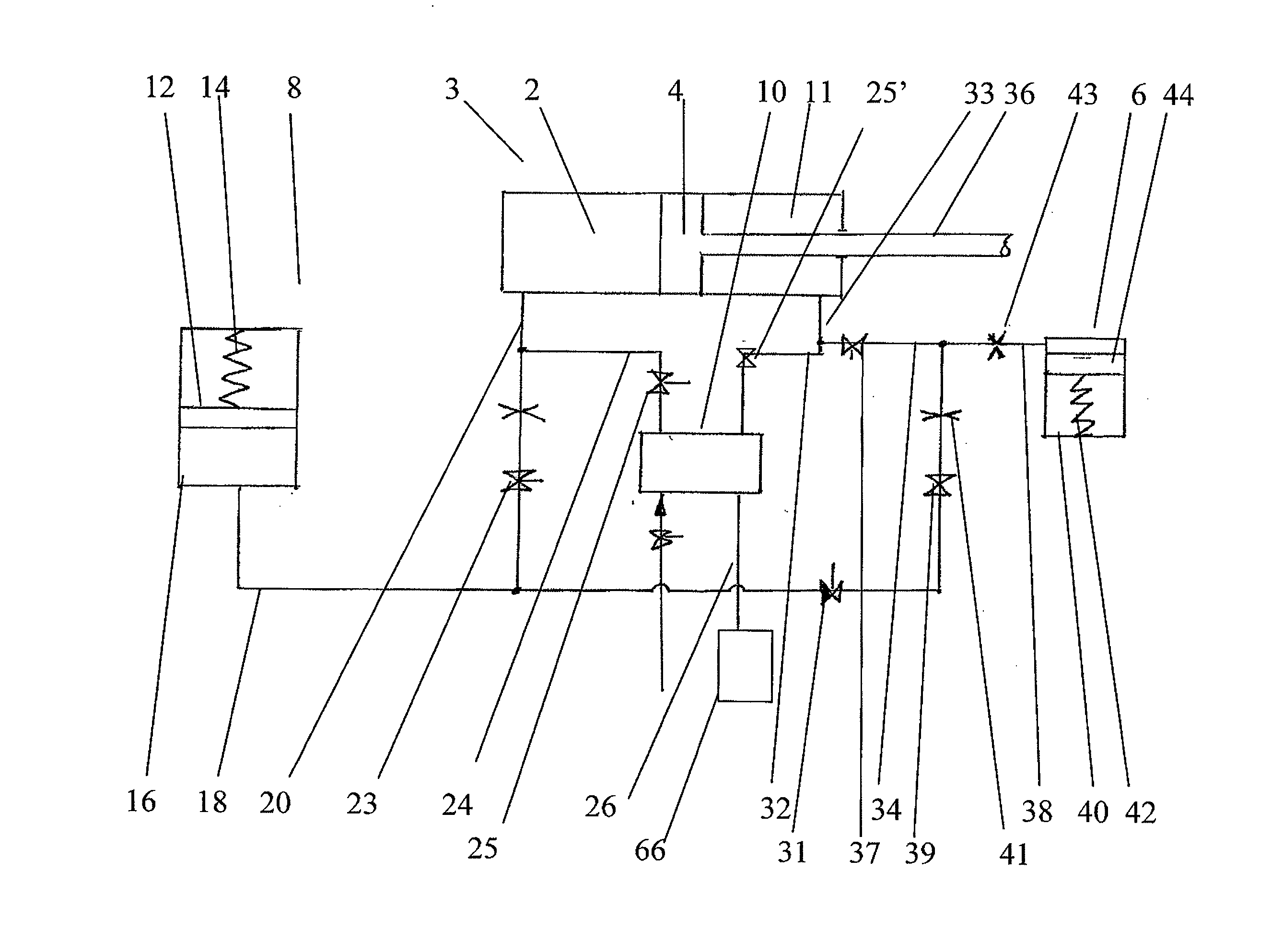
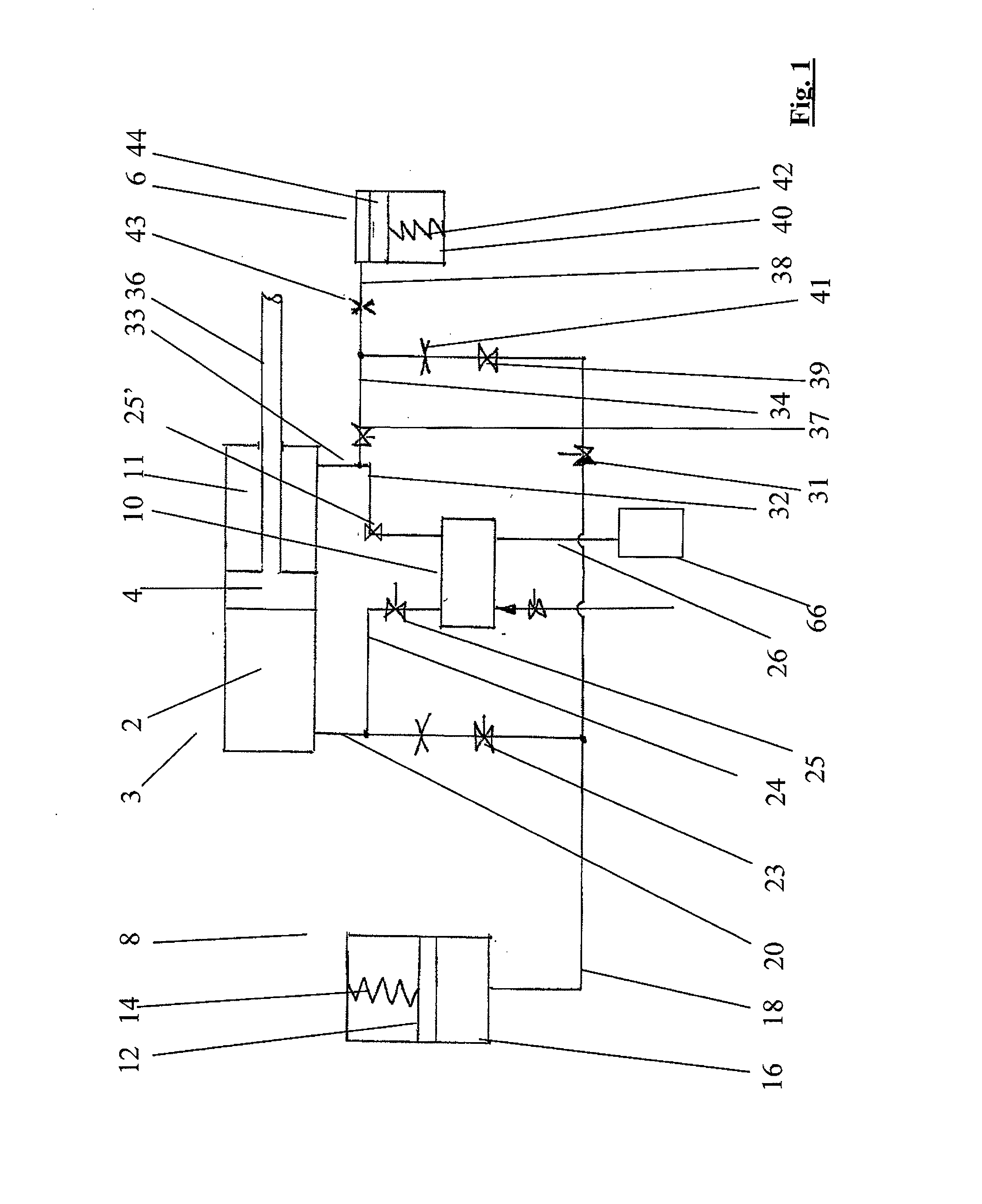
[0013]The objects of the present invention is accomplished by a system for driving a wind turbine blade of a wind turbine rotor, the system having a first pitch driving system configured for adjusting the pitch of the blades during normal working conditions on the basis of a feedback signal from a pitch control system, wherein the system is configured to drive the blades with variable pitch velocity into a feathered ...


PUM


Abstract

A system for driving a wind turbine blade (46) into a feathered position during an emergency stopping process of a wind turbine rotor. The system comprises a hydraulic actuator (3) functionally connected to the blade (46) for changing the pitch of the blade (46) during movement of the hydraulic actuator (3) and an emergency accumulator (8) connected to the hydraulic actuator (3) for driving the hydraulic actuator (3) with fluid from the emergency accumulator (8). The emergency accumulator (8) comprises a resilient member for accumulating the fluid in the emergency accumulator (8) under resilient pressure or a weight member (74) comprising a weight member upon the fluid in the emergency accumulator. The resilient member (14) or weight member (74) is configured for driving the fluid out of the emergency accumulator due to the expansion or retraction of the resilient member.

Description

FIELD OF THE INVENTION [0001]The present invention relates generally to wind turbines and more specifically to a system for controlling at least one wind turbine blade pitch during a stopping process of a rotor in a wind turbine.BACKGROUND OF THE INVENTION [0002]With energy resources becoming gradually more limited and expensive, it makes an increasingly more attractive business case to produce wind power. Accordingly, during the recent years there has been increasing focus on alternative energy such as wind-generated electricity.[0003]When operating a wind turbine under normal conditions, the blades can usually be pitched to feathered position during stopping of the wind turbine. This can be done in controlled manner in most cases, but during emergency stops, in case of grid drop out, failure in generator or control system, the pitching of the blades in order to achieve the emergency stop can introduce severe uncontrolled loading.[0004]Whilst the turbine's blade pitch control syste...

Claims


Application Information

Patent Timeline
IPC IPC(8): F03D7/04
CPCF03D7/0224F03D7/0264F05B2260/406F05B2270/402F05B2270/604Y02E10/723F05B2270/1074F05B2260/76Y02E10/72F03D7/022
Inventor STEFFENSEN, ULRIK
Owner GAMESA INNOVATION & TECH SA
Why Eureka
Try Eureka