
Electrophoretic display device and packing structure thereof

a display device and display device technology, applied in the field of electrotrophoretic display devices, to prevent the generation of defective wiring of cofs

Inactive Publication Date: 2010-01-21
LG DISPLAY CO LTD
View PDF49 Cites 24 Cited by
  • Summary
  • Abstract
  • Description
  • Claims
  • Application Information

AI Technical Summary

Benefits of technology

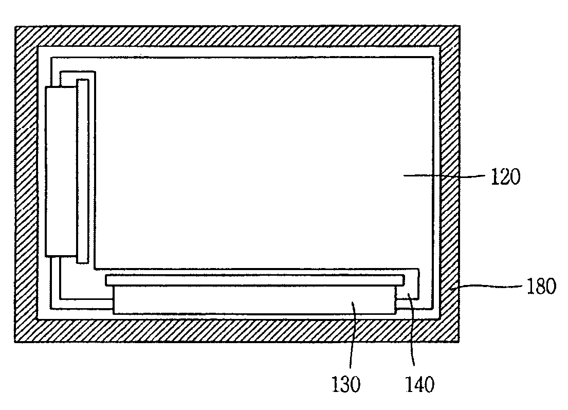
[0012]Therefore, in order to address the above matters, the various features described herein have been conceived. One aspect of the exemplary embodiments is to provide an electrophoretic display device capable of preventing generation of a defective wiring of a COF due to an impact resulting from wobbling while a packed electrophoretic display device is transported, by attaching the COF to a rear surface of a panel, packing the electrophoretic display device, and transporting it to a finished product manufacturer.
[0015]The present invention in which the COF, which is generally attached to a panel, is attached to a rear surface of the panel, has the following advantages.
[0016]That is, first, after the COF is attached to the rear surface of the panel, the electrophoretic display device is packed and transported to a finished product manufacturer, whereby generation of a defective wiring of the COF due to an impact resulting from wobbling while the packed electrophoretic display device is being transported can be prevented.
[0017]Second, upon receiving the electrophoretic display device with the COF attached to the rear surface of the panel, the finished product manufacturer does not need to perform a process of combining the COF to the rear surface of the panel to a frame, so the electrophoretic display device can be quickly assembled.
[0018]Third, because the COF is attached by the mold frame without the necessity of any extra frame, so the weight and the thickness of the electrophoretic display device can be reduced.

Problems solved by technology

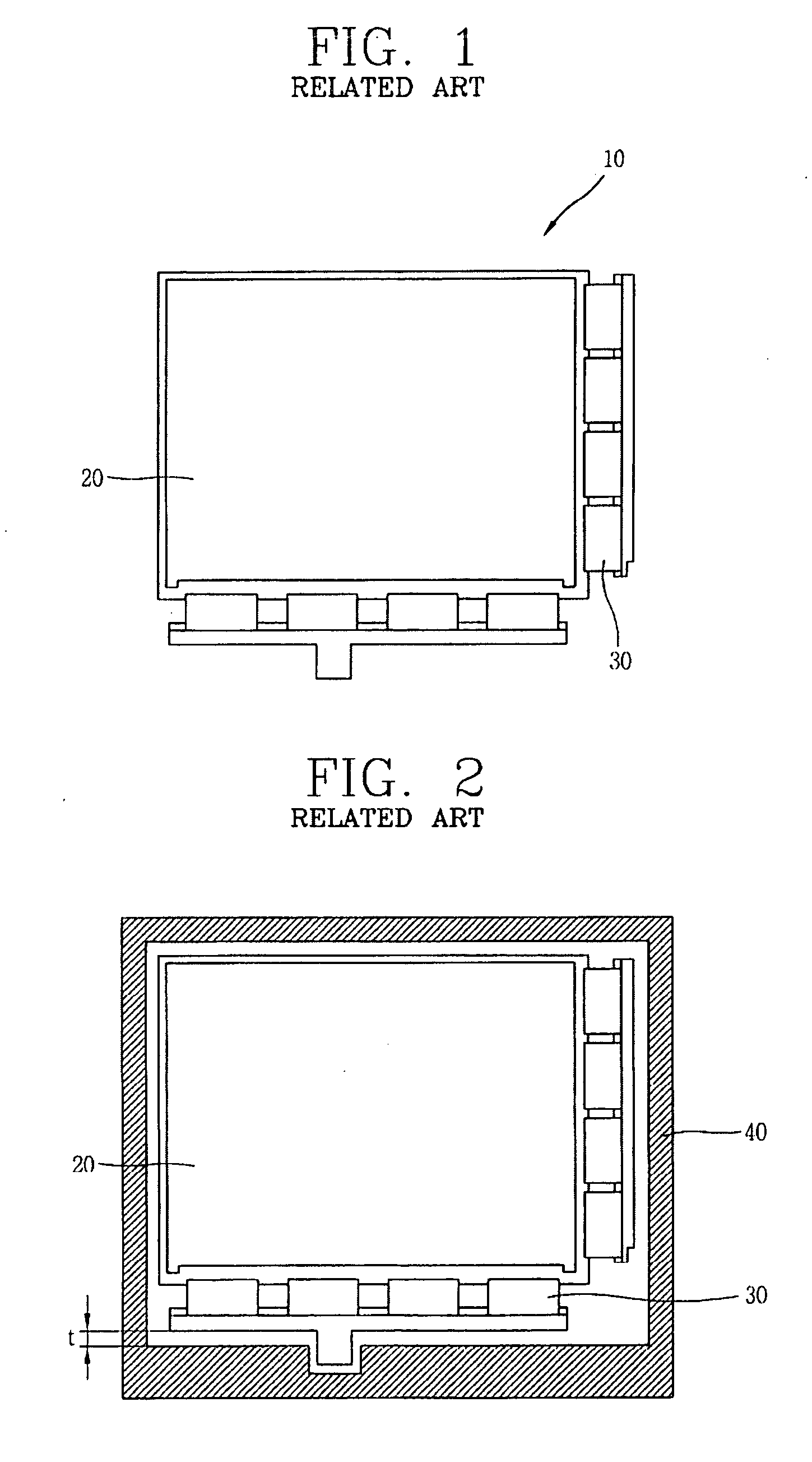
At this time, the related art electrophoretic display device has the following problem in transporting the module type electrophoretic display device.

Method used


Image

  • Electrophoretic display device and packing structure thereof
  • Electrophoretic display device and packing structure thereof
  • Electrophoretic display device and packing structure thereof

Examples


Embodiment Construction

[0028]An electrophoretic display device according to the present invention will now be described with reference to the accompanying drawings.

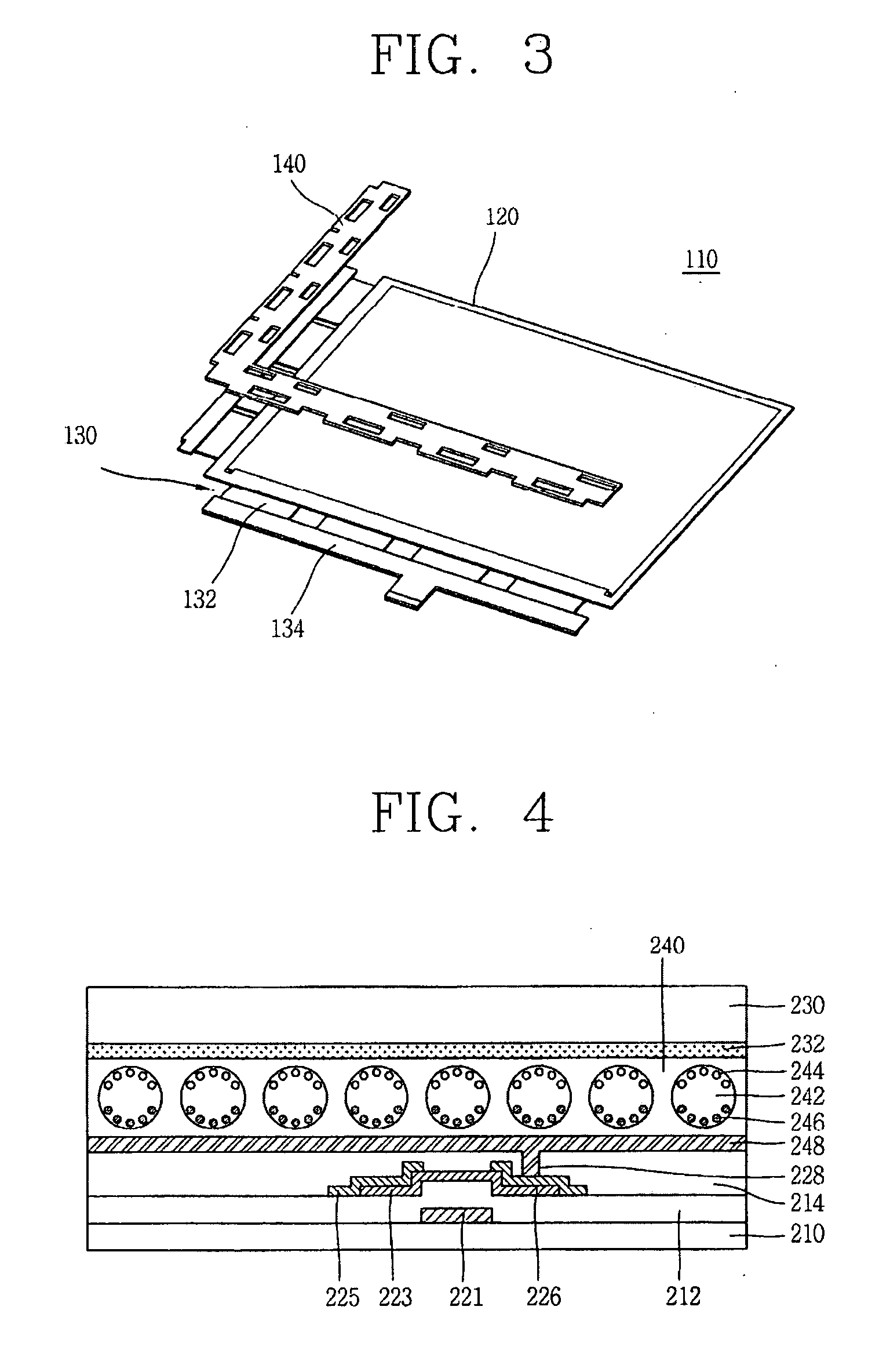
[0029]FIG. 3 is a view showing an electrophoretic display device according to an embodiment of the present invention.

[0030]As shown in FIG. 3, the electrophoretic display device 110 according to the present invention includes a panel 120 including electronic ink having white particles and black particles moving according to an application of a signal to implement an actual image, a COF 130 attached to the panel 120, having a driving element or the like thereon, and applying a signal to the panel 120, and a support frame 140 installed to the rear surface of the panel 120 and having the COF 130, which is folded toward the rear surface of the panel 120, attached thereto.

[0031]The COF 130 includes a film 132 and a printed circuit board (PCB) 134. The film 132, a TCP (Taped Carrier Package), includes a thin film transistor (TFT), driving circuits ap...


PUM

PropertyMeasurementUnit
timeaaaaaaaaaa
voltageaaaaaaaaaa
transparentaaaaaaaaaa

Abstract

An electrophoretic display device includes: an electrophoretic display panel; a COF (Chip On Film) attached to at least one side of the display panel and having a driving element mounted thereon; and a support frame installed on a rear surface of the electrophoretic display panel, wherein the COF is attached to the support frame through a double-sided tape.

Description

[0001]The present disclosure relates to subject matter contained in priority Korean Application 10-2008-0070337, filed on Jul. 18, 2008, which is herein expressly incorporated by reference in its entirety.BACKGROUND OF THE INVENTION[0002]1. Field of the Invention[0003]The present invention relates to an electrophoretic display device and, more particularly, to an electrophoretic display device including a support frame provided on its rear surface to allow a film with a driving element mounted thereon to be attached to the support frame to thereby prevent damage of the film due to wobbling of the electrophoretic display device when the electrophoretic display device is packed and moved.[0004]2. Description of the Related Art[0005]In general, an electrophoretic display device is an image display device using a phenomenon that when a pair of electrodes to which voltage is applied are put in a colloidal solution, colloidal particles move to one polarity. Because the electrophoretic dis...

Claims


Application Information

Patent Timeline
Patent Type & Authority Applications(United States)
IPC IPC(8): G09G3/34G02F1/167G02F1/16753
CPCG02F1/13452G02F2202/28G02F1/167G02F1/16753H01L23/4985G02F2201/42
Inventor PARK, SANG-HYUN
Owner LG DISPLAY CO LTD
Learn More