Eureka AIR delivers breakthrough ideas for toughest innovation challenges, trusted by R&D personnel around the world.

Method for operating a hybrid drive

Inactive Publication Date: 2010-01-21
ROBERT BOSCH GMBH
View PDF7 Cites 12 Cited by
  • Summary
  • Abstract
  • Description
  • Claims
  • Application Information

AI Technical Summary

Benefits of technology

[0008]The drag torque able to be absorbed by the electrical machine device is advantageously determined as a function of operating parameters of the electrical machine device. The absorbable drag torque is also limited, of course, by the design and / or dimensioning of the electrical machine device, but the operating parameters of the entire electrical machine device, that keep changing, require special consideration. In that way, damage to the electrical machine device is able to be prevented from the start, the control unit of the vehicle evaluating the operating parameters and correspondingly operating the separating clutch.
[0009]The state of at least one electrical storage unit associated with the electrical machine device is expediently used as the operating parameter. In this context, the temperature and the charging potential of the electrical storage unit are preferably observed. Consideration of the temperature of the electrical storage unit prevents overheating, and with that the destruction of the unit that goes along with it. By observing the charge potential, or rather the possible charge potential, it is prevented that the storage unit is charged above and beyond its charge capacity, based on the generator operation. This would also have destructive consequences for the storage unit.
[0010]The operating temperature of an electric machine associated with the electrical machine device is advantageously taken into consideration as the operating parameter, so that it is not overheated and destroyed in the process. In addition, the efficiency of the electric machine deteriorates with increasing temperature. This may also be taken into account by the method according to example embodiments of the present invention. The temperature of the internal combustion engine or, in the case of a hydraulic hybrid, the temperature of a component of the hydraulic system, may also be taken into account.
[0017]According to example embodiments of the present invention, the setpoint torque is specified as a function of the state of the separating clutch. Thus, the setpoint torque will turn out higher when the separating clutch is open, since in order to achieve the specifiable drag torque alone, the electrical machine device is used, and no torque loss can be used from the internal combustion engine. If the clutch is closed, the setpoint torque turns out correspondingly lower. Thus it is possible to implement the specified drag torque independently of the state of the separating clutch.
[0019]When the separating clutch is separated, the internal combustion engine is advantageously shut down, whereby in addition the fuel consumption of the hybrid drive device is lowered.
[0021]If, on the other hand, there is less emphasis on driving comfort, or the recoverable kinetic energy is to be as high as possible, in order to avoid a jolt, only a first small braking torque is specified at first. The braking torque of the electric machine is then increased after some time, up to a maximum value or the standstill of the vehicle. The additional recovered energy obtained thereby is used for charging the energy storage device. This embodiment of the present invention is particularly advantageous to use in driving cycles having frequent start-ups and braking.

Problems solved by technology

In particular after a cold start, the decelerating torque is particularly large because of great frictional losses.
In a hybrid vehicle that has a separating clutch between the internal combustion engine and the electrical machine or the hydraulic machine, the clutch may be separated, so that the internal combustion engine no longer has an influence on the remaining drive train, or rather is no longer operatively connected to it.
The absorbable drag torque is also limited, of course, by the design and / or dimensioning of the electrical machine device, but the operating parameters of the entire electrical machine device, that keep changing, require special consideration.
This would also have destructive consequences for the storage unit.
In addition, the efficiency of the electric machine deteriorates with increasing temperature.
If, during travel, air conditioning is switched on for example, the related air conditioner compressor has the effect of a further torque loss in the drive train, which has an effect on the drag torque.

Method used


Image

  • Method for operating a hybrid drive
  • Method for operating a hybrid drive
  • Method for operating a hybrid drive

Examples


Embodiment Construction

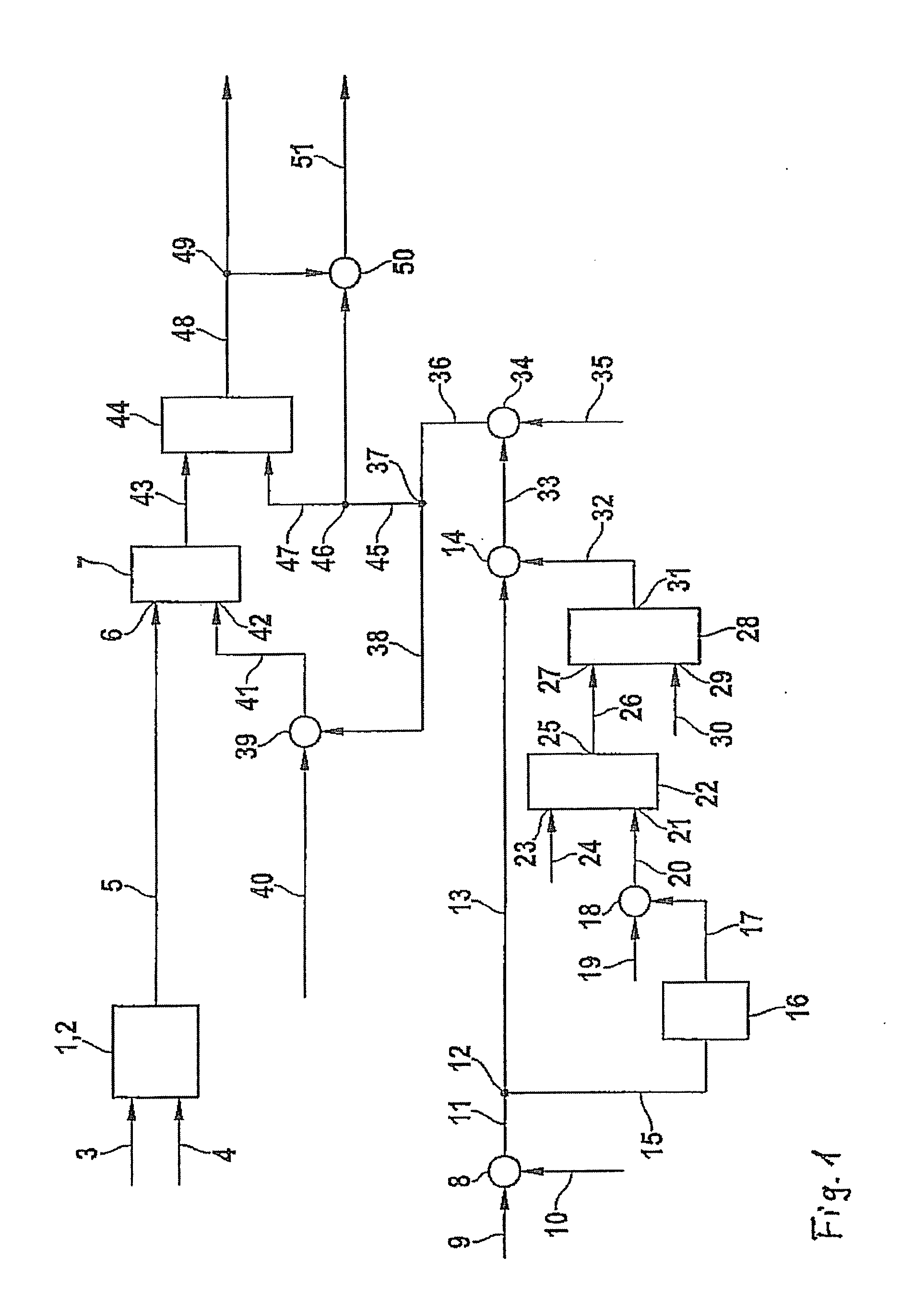
[0026]The block diagram in FIG. 1 schematically shows an exemplary embodiment of the method according to the present invention for an electric hybrid. The block diagram shows an element 1 which, for example, represents a control unit 2 of a hybrid drive device, and which calculates a drag torque specification for the hybrid drive device, using at least one stored characteristics map or characteristics curve. A drive train is involved in the hybrid drive device under discussion, having an internal combustion engine and an electrical machine device, the internal combustion engine and the electrical machine device being operatively connected using a separable separating clutch.

[0027]The control unit receives a signal, via a connection 3, which reproduces the speed of the vehicle, and it receives a signal via a connection 4, that tells which gear of a transmission of the drive device is engaged. From incoming signals 3 and 4 and the stored characteristics map or characteristics curve, c...


PUM


Abstract

A method for operating a hybrid drive, developed as a parallel hybrid, and having a drive train, especially for a motor vehicle, having at least one internal combustion engine and at least one electrical machine device or a hydraulic machine device, a separating clutch being situated between the internal combustion engine and the electrical or hydraulic machine device and, as seen in the drive direction, the electrical or the hydraulic machine device is postconnected to the internal combustion engine, the separating clutch being separated in the overrun condition if a specifiable drag torque is able to be absorbed by the electrical or the hydraulic machine device.

Description

FIELD OF THE INVENTION[0001]The present invention relates to a method for operating a hybrid drive, developed as a parallel hybrid drive, and having a drive train, especially for a motor vehicle, having at least one internal combustion engine and at least one electrical or hydraulic machine device, between the internal combustion engine and the electrical or hydraulic machine device a separating clutch being able to be situated and, as seen in the drive direction, the electrical or the hydraulic machine device being postconnected to the internal combustion engine.BACKGROUND INFORMATION[0002]At speeds of a motor vehicle greater than zero, if a driver does not operate the accelerator, he normally expects that the vehicle is decelerating, even if he is not operating the brake. In one conventional vehicle, whose drive unit is only an internal combustion engine, the deceleration is determined by a decelerating torque that is created by the nonfunctioning internal combustion engine that i...

Claims


Application Information

Patent Timeline
IPC IPC(8): F02B61/00B60L50/16B60W30/18
CPCB60K6/12Y02T10/642B60L2240/425B60L2240/445B60W10/02B60W10/06B60W10/08B60W20/00B60W30/18127B60W2510/0676B60W2510/087B60W2510/244Y02T10/6208Y02T10/6221Y02T10/6282Y02T10/6286B60K6/48B60L15/2054B60L2240/423B60L50/16Y02T10/62Y02T10/64Y02T10/7072Y02T10/72B60W20/40Y02T10/70
Inventor ANZ, RUPRECHTWERNER, MICHAELFAUTZ, OLIVERGLORA, MICHAEL
Owner ROBERT BOSCH GMBH
Why Eureka
Eureka Blog
Learn More