
Roll-forming machine for forming smooth curves in profiled panel sections and method of forming curved panels

Inactive Publication Date: 2010-01-21
METFORM INT
View PDF37 Cites 0 Cited by
  • Summary
  • Abstract
  • Description
  • Claims
  • Application Information

AI Technical Summary

Benefits of technology

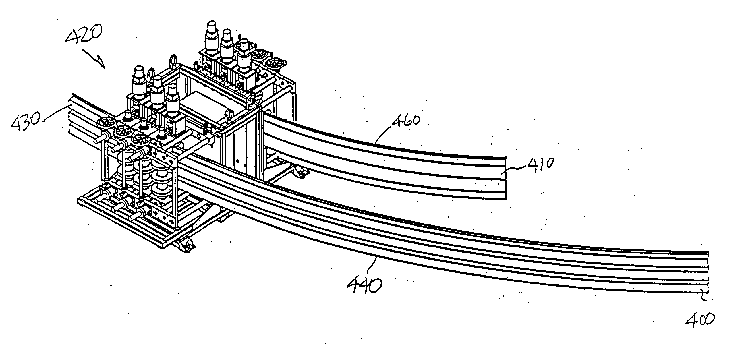
[0009]Therefore, according to the present invention there is provided a roll forming apparatus for the longitudinal bending of panels having complex cross sectional profiles. The present invention in one embodiment includes a hand-operated adjustment to permit the degree of curve formed in the panel to be varied and provides for a positioning of the rollers so that the smooth curve can be formed in a single pass. The present invention can impose either a concave or convex curve, by simple adjustment of the bending mechanism. The components of the present invention are arranged to permit the multiple bending arrangements to be easily and quickly implemented.

Problems solved by technology

Roll formed panel sections are well suited for use as roof or wall panel elements or exterior cladding elements, but are not easy to curve in longitudinal curves as required for such modern architecture.
Due to the corrugations, panels with complex cross-sectional profiles are not that easy to bend.
While this method can be used it suffers from several disadvantages, including that it is difficult to achieve the desired profile because the spacing and degree of bend of each angular increment needs to be precisely determined to achieve a panel that is appropriately curved according to the desired tolerances.
This type of press break machinery is also heavy machinery located in a fabrication facility, so any miss fitting panel sections have to be returned to the fabrication shop for reshaping, or simply discarded, which is expensive and time consuming.
Further the finished product is formed with many creases and so looks busy and unsightly.
Once again it can be difficult to get the right degree of longitudinal curve and if it is not right, it will require a trip back to the fabrication shop to rework the panel section to develop the proper curve.
This device has the advantage of forming a smooth rather than a creased curve, which can be considered to be an advantage over the first prior art method discussed above, but it has the disadvantage of requiring many passes, which is time consuming, expensive and difficult to reliable repeat.
Matching separately formed curved panel sections to curved liners has been difficult to achieve up until the present.

Method used


Image

  • Roll-forming machine for forming smooth curves in profiled panel sections and method of forming curved panels
  • Roll-forming machine for forming smooth curves in profiled panel sections and method of forming curved panels
  • Roll-forming machine for forming smooth curves in profiled panel sections and method of forming curved panels

Examples


Embodiment Construction

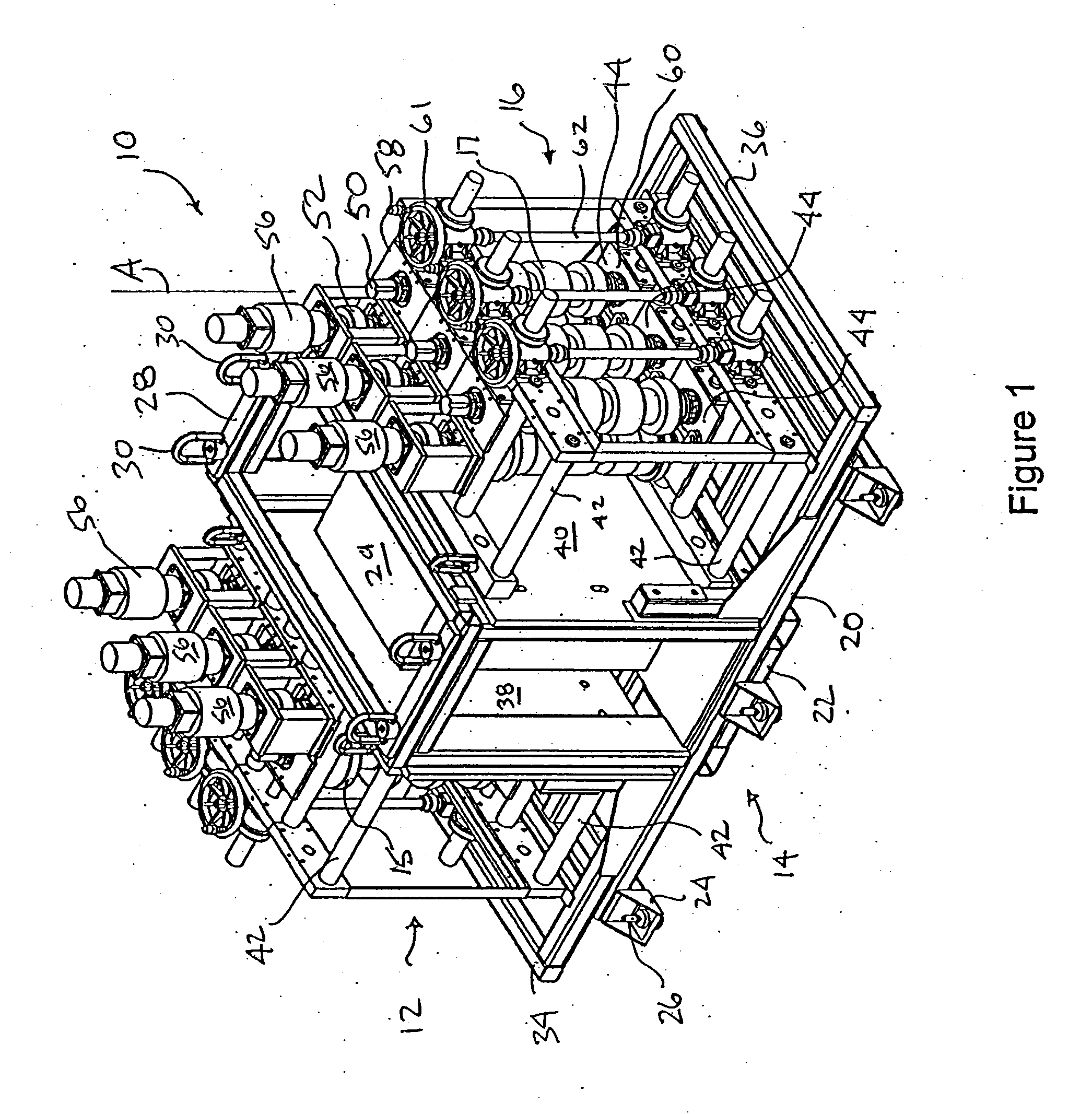
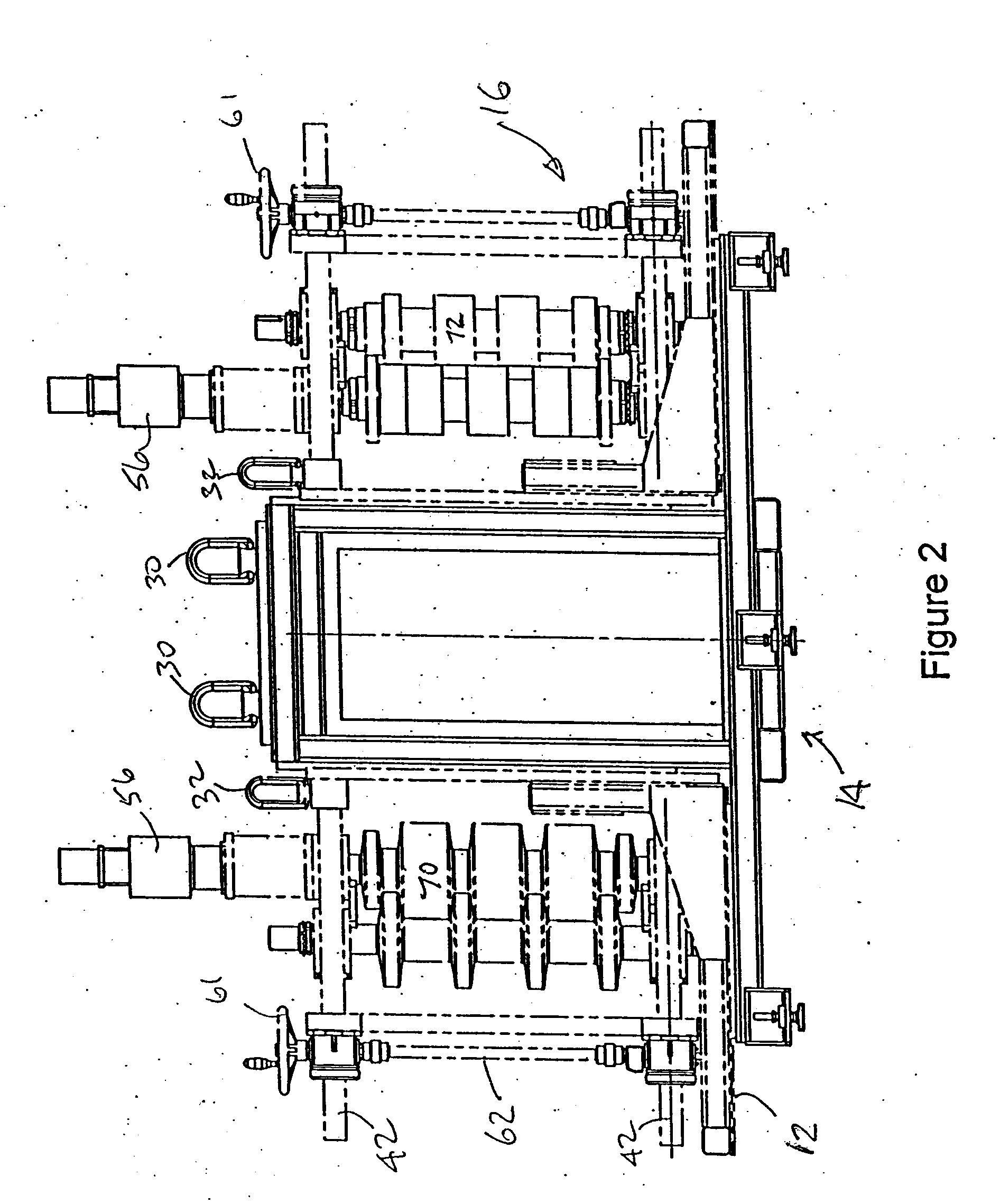
[0024]A panel curving apparatus for roll forming smooth longitudinal curves in profiled panel sections according to the present invention is shown generally as 10 in FIG. 1. The preferred curving apparatus 10 includes three main sections, namely a first tooling raft 12, a central instrumentation and control station 14 and a second tooling raft 16. As will be explained in more detail below the first and second tooling rafts 12, 16 are generally similar in operation, but may be provided with different roller tooling configurations to facilitate the use of the invention. For example, in one preferred embodiment the first tooling raft 12 can have rollers 15 that are suitable for N-Decking type panel material and the second tooling raft can have rollers 17 that are suitable for a liner panel for the N-Decking panels of the first tooling raft. It will be noted from FIG. 1 that the rollers are oriented on a generally vertical axis of rotation for example as shown at A for reasons explained...


PUM


Abstract

A roll-forming machine for forming smooth curves in profiled panel sections. The roll forming machine has opposed pinch pass rollers having a roller profile generally corresponding to said profiled panel and a pair of cantilever rollers downstream of said pinch pass rollers. The cantilever rollers have axes of rotation that are offset relative to one another in the direction of travel of the profiled panel through the machine and having a roller profile also generally corresponding to the profiled panel. At least one sweep roller is positioned downstream of the cantilever rollers for bending said panel in a longitudinal direction as said panel passes past said sweep roller. The sweep roller also has a roller profile generally corresponding to the profiled panel. The at least one sweep roller can be positioned to the degree of bend of the smooth curve formed in said profiled panel by the machine.

Description

FIELD OF THE INVENTION[0001]This invention relates generally to the field of roll forming, and more particularly to methods and apparatuses for working with roll formed panels.BACKGROUND OF THE INVENTION[0002]Roll forming is an industrial process whereby flat sheets of material can be bent in cross section to attain a corrugated or bent cross sectional profile in a longitudinal panel. Typically roll forming machines consist of pairs of opposed rollers that are shaped to introduce the desired cross-sectional bends into the panel sections. One roller of the roller pair is usually a driven roller and a series of roller pairs are placed along the length of the roll forming machine to effect the required bending in the panel section as it progresses through the roll forming apparatus. Each roller of the opposed roller pair will have a matching or interfacing set of rollers to gently bend the panel cross section into the desired final configuration.[0003]Many configurations of roll formin...

Claims


Application Information

Patent Timeline
IPC IPC(8): B21D13/04
CPCB21D7/08
Inventor TRUONG, MINHOPIELKA, JACEKKUMAR, VINOD
Owner METFORM INT
Learn More