System and Method for Clock Offset Detection

Active Publication Date: 2010-01-14
TEXAS INSTR INC
View PDF17 Cites 12 Cited by
  • Summary
  • Abstract
  • Description
  • Claims
  • Application Information

AI Technical Summary

Benefits of technology

[0010]In accordance with another embodiment, a display system is provided. The display system includes a display that produces images by modulating light based on image data, an image input providing an analog image signal comprising the image data, an image processing unit coupled to the image input, and a controller coupled to the image processing unit and to the display. The image processing unit digitizes the analog image signal and reduces a sampling frequency offset in a first sampling frequency of the analog image signal and a second sampling frequency of the image processing unit, wherein the image processing unit computes the sampling frequency offset by computing values of an autocorrelation function with samples of the analog image signal and a delayed version of samples of the analog image signal, wherein the computing is performed for a range of delays. The controller controls the operation of the display based on the image data.
[0016]A further advantage of an embodiment is that multi-pass techniques (multiple iterations) may be employed to achieve a more accurate determination of the sampling frequency offset while still requiring a relatively short amount of time.

Problems solved by technology

If the sampling frequency is incorrectly detected, then when the digitized images are displayed, the resulting images may be distorted at best or completely incomprehensible at worse.
The presence of a sampling frequency offset may result in the appearance of a vertical interference pattern on images displayed by the image display system. FIG. 1a illustrates an image frame 100 from an analog image signal.

Method used


Image

  • System and Method for Clock Offset Detection
  • System and Method for Clock Offset Detection
  • System and Method for Clock Offset Detection

Examples


Embodiment Construction

[0043]The making and using of the embodiments are discussed in detail below. It should be appreciated, however, that the present invention provides many applicable inventive concepts that can be embodied in a wide variety of specific contexts. The specific embodiments discussed are merely illustrative of specific ways to make and use the invention, and do not limit the scope of the invention.

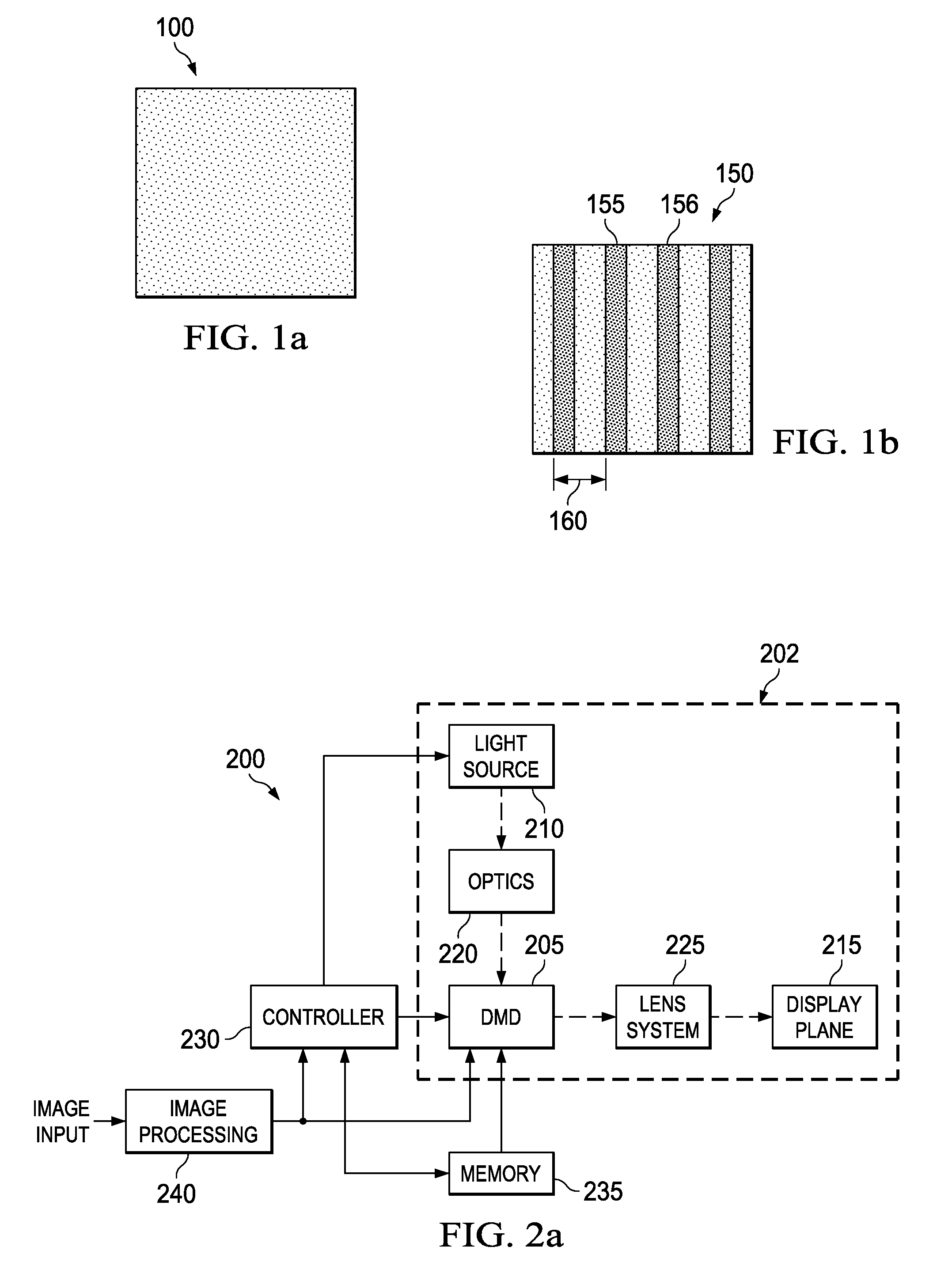
[0044]The embodiments will be described in a specific context, namely a digital micromirror device (DMD) microdisplay-based image projection display system connected to an analog image source, such as a computer. The invention may also be applied, however, to other forms of analog image sources, such as analog video tape, analog DVDs, analog game console output, analog electronic video sources, such as multimedia players and sources, and so on. Furthermore, other forms of microdisplay-based image projection display systems, such as deformable micromirrors, liquid crystal on silicon (LCOS), ferro...


PUM


Abstract

A system and method for detecting a sampling clock offset of an analog-to-digital converter used to digitize an analog image signal. A method comprises buffering samples of an analog image signal, computing a value of an autocorrelation function using the buffered samples and a delayed version of the buffered samples, and repeating the computing a value for delays in a range of delays. The method also comprises computing a sampling frequency offset from the values of the autocorrelation function and changing a sampling frequency using the sampling frequency offset.

Description

CROSS-REFERENCE TO RELATED APPLICATIONS[0001]This application is related to the following co-assigned patent applications: U.S. Patent Publication Number 2006 / 0274194 A1, filed Feb. 16, 2006, entitled “Method and Apparatus for Analog Graphics Sample Clock Frequency Offset Detection and Verification,” Ser. No. 12 / 101,685, filed Apr. 11, 2008, entitled “System and Method for Detecting a Sampling Frequency of an Analog Video Signal,” Attorney Docket Number TI-65745, filed ______ 2008, entitled “System and Method for Tuning a Sampling Frequency,” which applications are hereby incorporated herein by reference.TECHNICAL FIELD[0002]The present invention relates generally to a system and method for displaying images, and more particularly to a system and method for detecting a sampling clock offset of an analog-to-digital converter used to digitize an analog image signal.BACKGROUND[0003]In many modern image display systems, image frames of an analog image signal, such as analog video, analo...

Claims


Application Information

Patent Timeline
IPC IPC(8): H03M1/12
CPCG09G3/001G09G3/2096H04N5/04G09G2320/02H03M1/127G09G5/008
Inventor OUYANG, BINGHAYDEN, JOHN MICHAELETHRIDGE, TROY LANECHO, HONG JINKORDEL, JEFF
Owner TEXAS INSTR INC
Why Eureka
Try Eureka