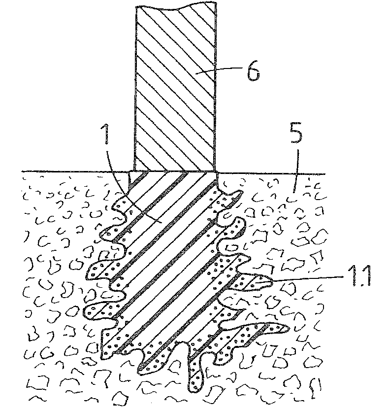
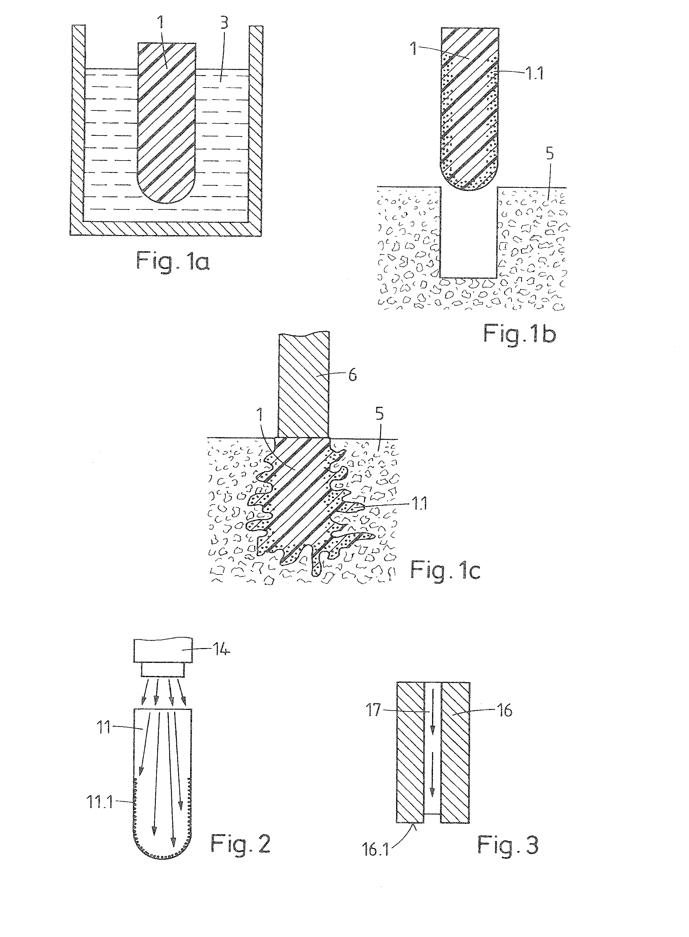
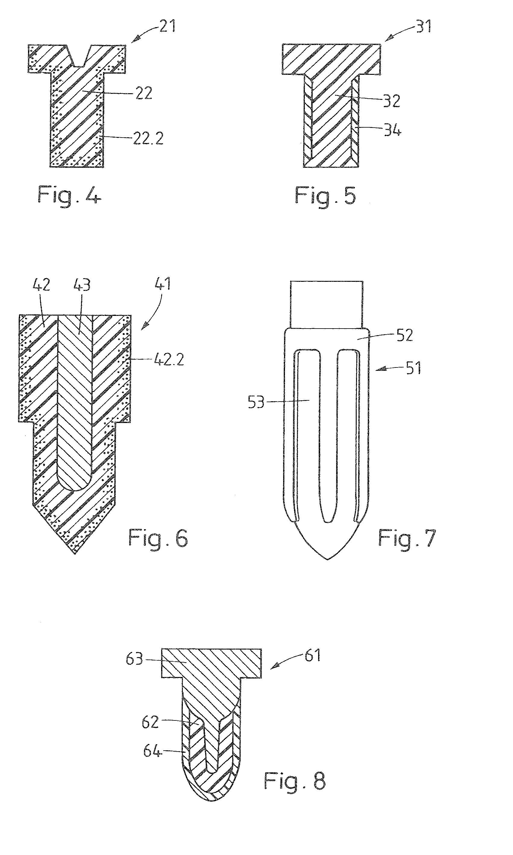
[0008]It is an object of this invention to provide an implant (or element for endodontic use) and methods of implanting an implant and of preparing an implant, which overcome drawbacks of prior art implants and methods. It is also an object of the invention to provide an implant and a method of implanting an implant by means of
mechanical vibration, which method provides a high primary stability of the connection to the tissue it is implanted in. The implant should also be suited for soft, spongy and / or brittle tissue and for implantation with little force.
[0009]The method and implant according to a first aspect of the invention make use of the concept that the implant includes portions of thermoplastic material, preferably in the vicinity of a surface, which material portions are above their
glass transition point when the mechanical vibrations act and therefore have a high absorptivity for
mechanical energy. In addition, the implant includes thermoplastic material portions which are located adjacent to the above named material portions and which do not have a high absorptivity for mechanical energy. These material portions may include portions of a thermoplastic material that at the onset of the mechanical vibrations are below the glass
transition temperature, but which are all the same liquefiable by the mechanical vibrations. These additional material portions have a higher modulus of elasticity and thereby bring about a good transport of mechanical energy to the contact surfaces and also add to the stability of the implant and its connection to the tissue.
[0013]The material regions which are above the glass
transition temperature, when the mechanical vibrations start acting, are capable to serve as a kind of heater for adjacent thermoplastic material portions which are, when the vibrations start acting, below the glass
transition temperature. Therefore, not only the highly energy absorptive (second) material portions are liquefied more easily, but also adjacent (first) material portions of the “harder”, initially less absorptive thermoplastic material are liquefied more easily due to the
heating effect by the second material. This effect is enhanced, if the “harder”, first thermoplastic material, which is initially less absorptive, has a glass transition temperature not too far above an implantation or body temperature (e.g. about 37° C.), i.e. a glass transition temperature of e.g. between 37° C. and 150° C. In this case, portions of the first material which by being situated adjacent the second material are heated above the glass transition temperature by the second material, and therewith get an enhanced absorptivity also. This means that the portions of the second material can be very small. They may be viewed as decreasing the
activation energy for
liquefaction of the “harder” first material portions, thus as a kind of “catalyst”. Preferably the second material portions are small compared with the volume of the implant or of the first material portions such that the less advantageous mechanical properties of this second material, if they are not wearing off, see further below, have only a minor effect on the
mechanical stability of the connection between implant and bone.
[0042]Different aspects of the invention bring about the
advantage that by a chosen arrangement of first and second material portions, or by a chosen concentration profile of a
plasticizer, or other means of bringing thermoplastic material above its glass transition temperature, it is possible to define regions where the implant, when subject to the mechanical energy, starts liquefying. This may even be independent of the quality of adjacent tissue and may even be independent on contact forces etc. Therefore, the approach according to the invention brings about the
advantage of supporting implantation in situations where no or almost no
contact force can be applied, where the tissue is very weak, where the liquefiable material is to be melted at places not in contact with
hard tissue /
hard tissue replacement material (for example in a ‘blind
rivet’ fashion) etc. This applies both, to otherwise conventional, pin-like implants and forward implantation, and to newly developed implants / implantation methods, as for example described in patent applications PCT / CH 2007 / 000459 (based on 60 / 826,300), and U.S. 60 / 983,791, all incorporated herein by reference.
[0051]In this, the (second) more easily liquefiably material portions (according to either one or combination of the aspects of the invention) of liquefiable material may constitute the liquefiable material at at least one of the first and the second contact face, or may constitute a portion thereof—for example at a place where enhanced
liquefaction is desired—, and / or it may be present at a location different from the contact faces to further
liquefaction at such locations different from the contact faces.
[0064]The
thermoplastic materials may contain foreign phases or compounds serving further functions (if applicable, a light absorbing function as mentioned further above or an even further function combined with a light absorbing function). In particular, the thermoplastic material may be strengthened by admixed fibers or
whiskers (e.g. of
calcium phosphate ceramics or glasses) and such represent a
composite material. The thermoplastic material may further contain components which expand or dissolve (create pores) in situ (e.g. polyesters, polysaccharides, hydrogels,
sodium phosphates) or compounds to be released in situ and having a
therapeutic effect, e.g. promotion of healing and regeneration (e.g. growth factors,
antibiotics,
inflammation inhibitors or buffers such as
sodium phosphate or
calcium carbonate against adverse effects of acidic
decomposition). If the thermoplastic material is resorbable, release of such compounds is delayed.


