
Bipolar membrane for electrochemical supercapacitors and other capacitors

a supercapacitor and bipolar membrane technology, applied in the field of capacitors and supercapacitors, can solve the problems of carbon taking the place of the improved insulators, the inability of supercapacitors to deliver full charges, and the negative impact of capacitor life, so as to reduce or eliminate the self-discharge of capacitors and maintain the separation of charges

Inactive Publication Date: 2009-12-24
GAS TECH INST
View PDF13 Cites 11 Cited by
  • Summary
  • Abstract
  • Description
  • Claims
  • Application Information

AI Technical Summary

Benefits of technology

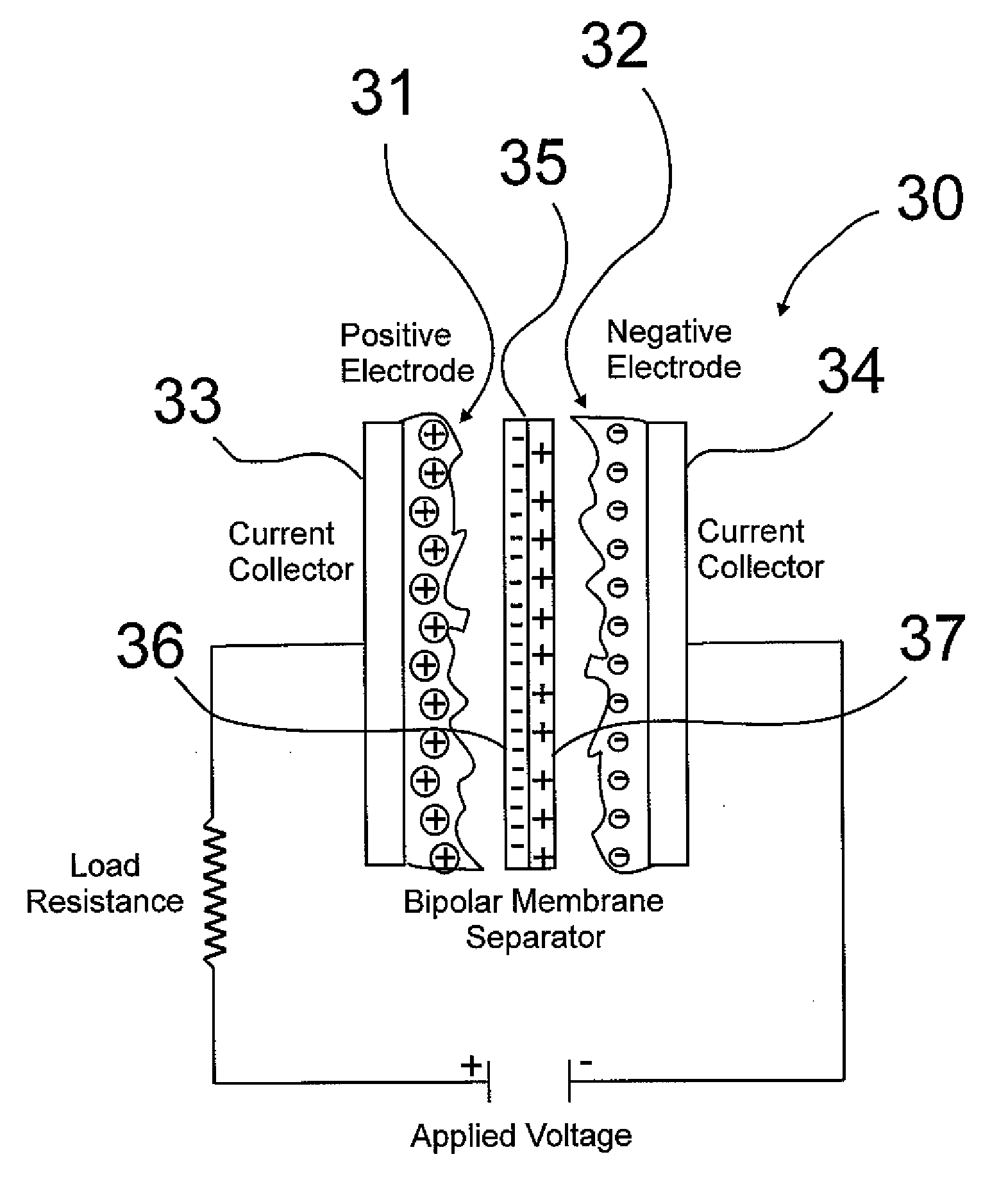
The invention provides a method and apparatus for reducing or eliminating the self-discharge of capacitors, particularly supercapacitors for energy storage. This is achieved by using a separator element in the form of a bipolar membrane with cations and anions that selectively transport ions to the positive and negative electrodes, creating a sub-capacitor that maintains the separation of charges with little or no recombination. The bipolar membrane is placed between the positive and negative electrodes in an energy storage device, and a potential field is applied to split water into protons and hydroxyl ions, resulting in the production of acidic and basic solutions at the surface of the membrane. This results in a highly efficient and reliable energy storage device with reduced self-discharge.

Problems solved by technology

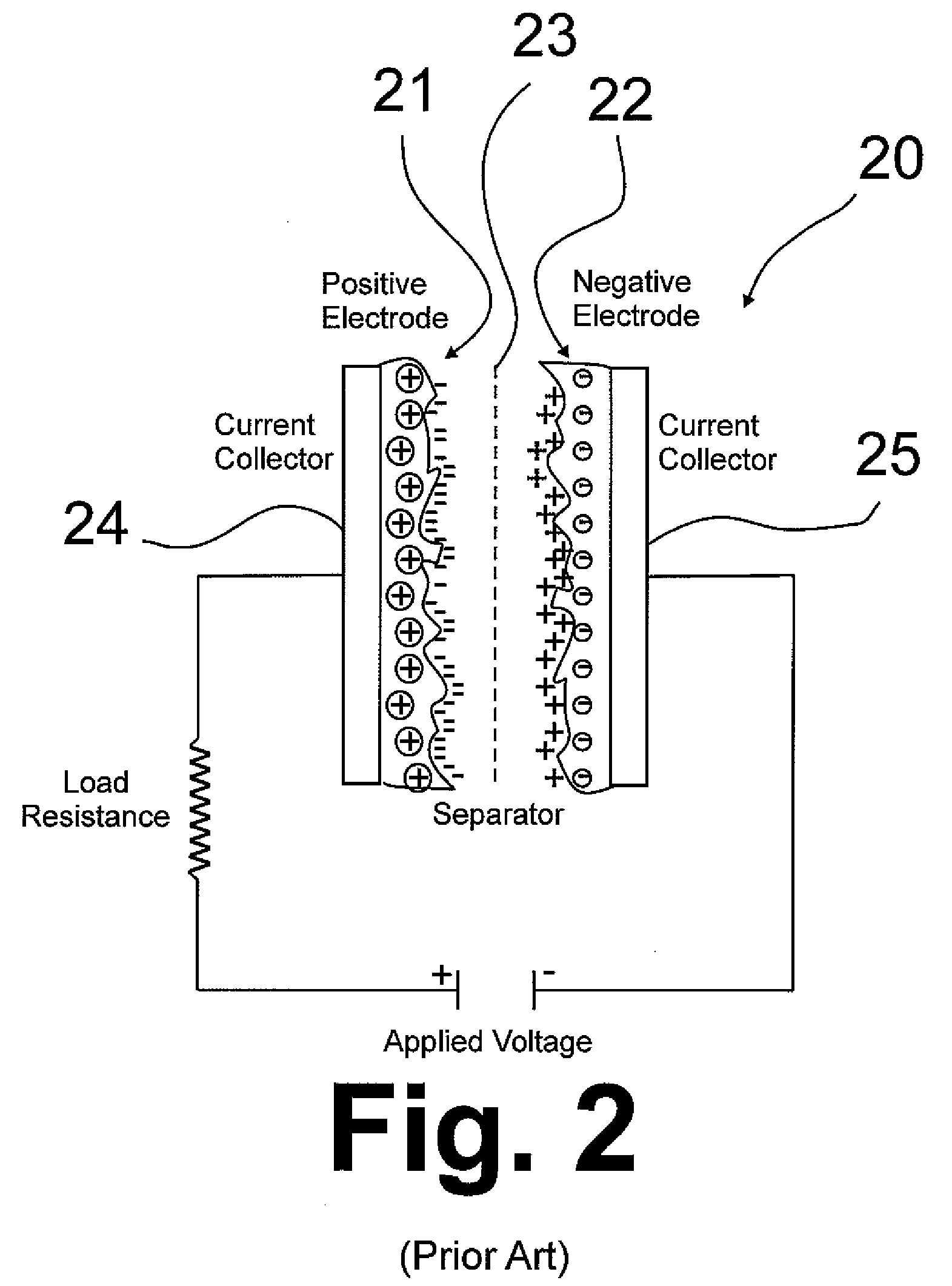
However, the double layer can withstand only a low voltage, which means that supercapacitors rated for higher voltages must be made of matched series-connected individual supercapacitors.
The disadvantage of using activated carbon is that the carbon is taking the place of the improved insulators used in conventional devices, as a result of which supercapacitors employ low potentials on the order of only 2 to 3 V.
As a result, supercapacitors are unable to deliver a full charge.
However, these methods negatively affect the lifetime of the capacitors.
Self-discharge not only affects the energy efficiency of the supercapacitor due to loss of charge, but also may affect the lifetime of the supercapacitor due to consumption of matter.
Clearly, this kind of process will affect the lifetime of the capacitor.

Method used


Image

  • Bipolar membrane for electrochemical supercapacitors and other capacitors
  • Bipolar membrane for electrochemical supercapacitors and other capacitors
  • Bipolar membrane for electrochemical supercapacitors and other capacitors

Examples


example 1

Supercapacitors Without Bipolar Membranes

[0032]In this example, graphite samples were made into a slurry with isopropanol and TEFLON® solution, table cast onto aluminum foil and heat treated at 365° F. for one hour. The resulting electrode contained about 40% by weight TEFLON as a binder. The foil 41, 42 was cut into 2″ by 2″ squares and sandwiched between gasket material 43, 44 and garolite plates 45, 46, forming a capacitor 50 as shown in FIG. 5 which was tested for double layer capacitance in a press. The capacitor was composed of two identical electrodes 47, 48 facing each other and separated by a piece of manila paper 49 having a thickness of about 4 mils. One gram of tetraethylammonia-hexaflorophosphate (TEAPF6) dissolved in 10 ml of acetonitrile resulting in a TEAPF6 concentration of about 11.5% was used as electrolyte. The pressure of the press 55 was maintained at 5 psig throughout the test. Cyclic voltamograms were taken between −1 to about +1V at a scan rate of 100 mV / sec...

example 2

Supercapacitor with Bipolar Membrane

[0033]A bipolar membrane was constructed from an anion exchange membrane and a cation exchange solution by way of a method in which the anion exchange membrane, e.g. polyolefin-amine based anion exchange membrane from Tokuyama, Japan having a thickness of about 25 μm, was spray coated with a 5 wt % NAFION® solution to form a NAFION layer having a thickness of about 1 μm. After drying at room temperature for about 12 hours, the resulting bipolar membrane was soaked in an electrolyte solution containing 1 gram of TEAPF6 dissolved in 10 ml of acetonitrile for 3 hours. The soaked bipolar membrane was placed between the two electrodes using XC72 carbon in the same manner as described in Example 1 to replace the manila paper as a separator. Cyclic voltamograms were taken between −1 to +1V at a scan rate of 100 mV / sec, 50 mV / sec, and 20 mV / sec. As before, at each scan rate, four cycles were recorded. Double layer currents at zero potential were taken, av...


PUM


Abstract

A supercapacitor having a bipolar membrane separator having a first side facing the negative electrode of the supercapacitor and having a plurality of cations and a second side facing the positive electrode and having a plurality of anions.

Description

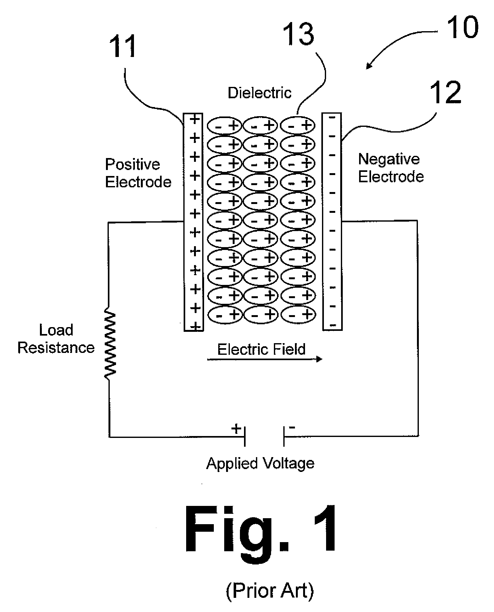
BACKGROUND OF THE INVENTION[0001]1. Field of the Invention[0002]This invention relates to a device for storing energy. In one aspect, this invention relates to capacitors and supercapacitors. In another aspect, this invention relates to a method and means for reducing or eliminating the self-discharge of capacitors and supercapacitors.[0003]2. Description of Related Art[0004]A capacitor, also referred to as a condenser, is an electric circuit element used to store charge (energy) temporarily, consisting in general of two metallic plates, i.e. positive and negative electrodes, separated and insulated from each other by a dielectric. In a conventional capacitor, energy is stored by the removal of charge carriers, typically electrons, from one metal plate and depositing them on the other metal plate. This charge separation creates a potential between the two plates, which can be harnessed in an external circuit. The total energy stored in this fashion (capacitance) is a combination of ...

Claims


Application Information

Patent Timeline
Patent Type & Authority Applications(United States)
IPC IPC(8): H01G9/016
CPCY02E60/13H01G9/02
Inventor FAN, QINBAI
Owner GAS TECH INST
Learn More